
The spanish company SISMO Soluciones has a really cool I/O board called SC-MB (SimCard Mother Board SC-MB Ethernet). It works on ethernet and allows to connect a series of daughter boards for extending digital inputs / outputs, analog inputs, servo outputs or seven segment displays. The wiring is much more elegant than for instance with the hardware of OpenCockpits. The SISMO SC-MB protocol is openly documented and I have been able to add it to my open source xpcockpit software.
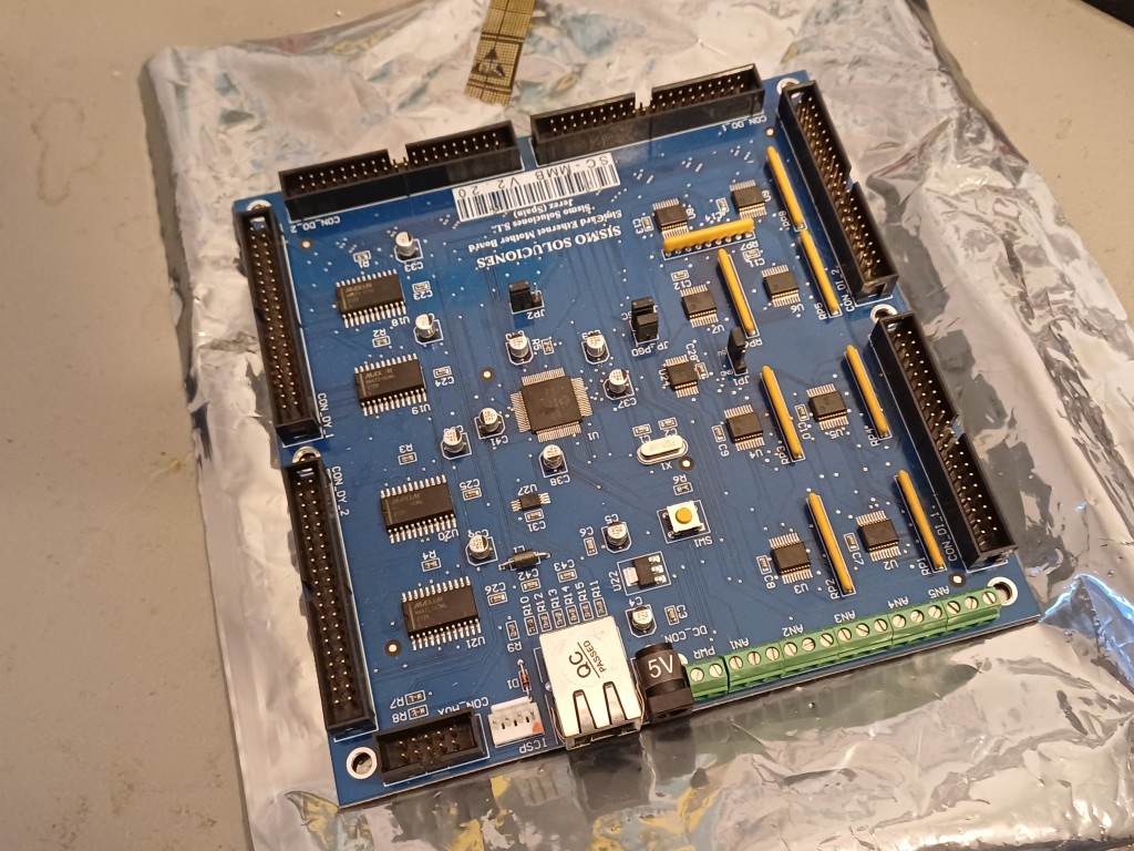
The SISMO Soluciones SC-MB
However, the original SC-MB firmware has a few drawbacks
- It sends its full input register 500 times per second to the UDP server application even if not a single switch was pressed. This generates unnecessary network overhead.
- If a daughter board is connected, the input polling interval decreases from 2 to around 4-5 milliseconds. This leads to missed encoder steps especially for optical encoders. It happens for instance when using the original SISMO MCP+EFIS combination.
- The analog inputs suffer from a regular A/D noise of around +/- 1 step. This leads to continuous sending of new analog input values.
- The IP address of the UDP server has to be pre-stored in the SC-MB. This does not work well with computers running on DHCP.
An new alternate firmware can correct this drawbacks
I have reverse engineered the hardware of the SC-MB and written an alternate firmware for it using MPLAB X IDE 6.30 and the Pickit 5 programmer. It corrects the above shortcomings by the following steps:
- Inputs are only sent back to the UDP server if an input changes. This relieves the network overhead. In a home flight simulator sometimes no input is changed until someone moves a switch.
- The input polling is always 1 millisecond, even if many daughter boards are connected via I2C. No more missed steps with encoders, even if you turn them rapidly. Actually, interrupted inputs would be the better solution, but I found it to be stable with 1 millisecond polling.
- A median filter is applied to analog inputs. Even if their values wobble by +/- 1 digital units, there is no data being sent back to the UDP server. Analog inputs are only sent back to the UDP server if they change consistently up or down.
- The SC-MB sends its data back to any sender contacting the board. No more need to pre-store the UDP server IP address in the SC-MB. You can however still pre-store a IP address if you want.
All features of the alternate firmware should be compatible with the SISMO UDP protocol and SISMO software. This is however untested as I use my own UDP server software.
How to apply the firmware?
Note that the following steps will delete the original firmware. You cannot read and save the original firmware since it is read protected on the chip. So you cannot undo the steps below. And SISMO Soluciones will not provide us with the original firmware, not even with the compiled one.
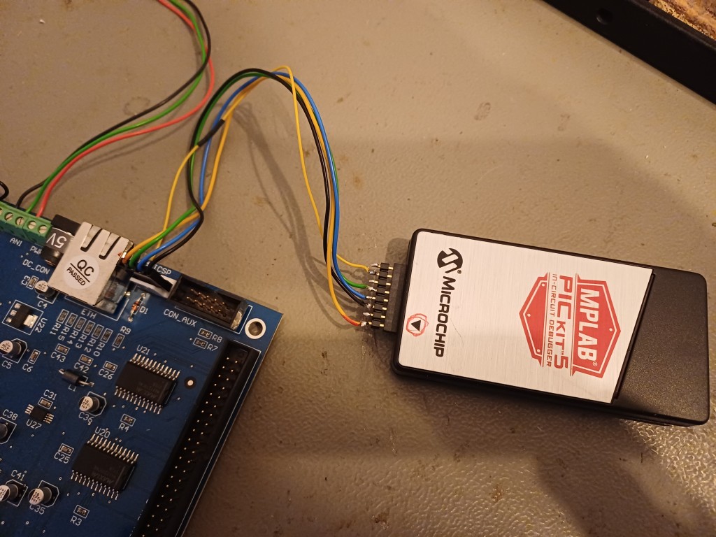
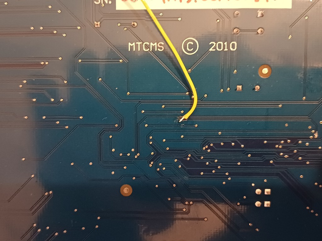
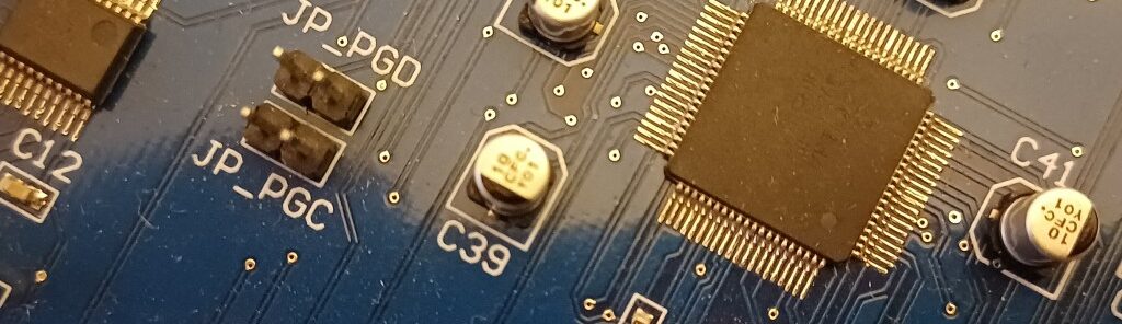
- Connect the 4 pin header of the SC-MB to the 8 pin header of your Pickit (upper left picture below). If you want UART Debugging, you will need to find and solder the UART TX pin of the PIC18F86J60 microcontroller and manually route it to the Pickit programmer (upper right picture below). I have no idea why SISMO Soluciones did not provide this pin on its programming header. It is super necessary during development and debugging. Then remmove the JP_PGC an JP_PGD jumpers (lower picture below). They make sure the multiplexed I/O does not interfere with the programming lines.
- Get the new firmware (Firmware.X) as a MPLAB X IDE project from my github repo. Open this Firware in MPLAB X IDE. I had to develop under MPLAB X IDE since the MCC routines for the old microcontroller PIC18F86J60 were not supported under VSCode. You should be able to program the firmware onto the chip easily. Make sure the board is powered and under project settings the Pickit programmer is powering the target device (selected) with 3.25V.
- Once programmed, you will need to store the device configuration (IP address, gateway, network mask, number and types of daughter cards. The original firmware provided a web service. The alternate firmware has a simple script called writeconfig.c which can be compiled and used to send the configuration data to the SC-MB. It can be found in the src directory of the xpsismo repo. The inidata directory of the xpsismo repo features a few .cfg files that are read by the writconfig.c code.
- Apply the JP_PGC and JP_PGD jumpers back in place.
You should be all set.
A few notes
- You can still specify a UDP server IP address if you want to stay compatible with e.g. SISMO Soluciones code. The Sismo Soluciones code expects the SC-MB to automatically send data to the UDP server. My alternate firmware expects the UDP server to initiate the communication so the SC-MB knows where to send the data.
- The above was all developed and tested on Linux. A few changes may be needed when running the writeconfig.c code on Windows or OSX. The PIC programming should work fine in MPLAB X IDE on Windows. The new firmware should be compatible with the SISMO Soluciones software packages, for instance when connecting to X-Plane / MSFS etc. However, I did not test it. I’d be glad if someone could test as I have never used the SISMO drivers and plugins. The new firmware works really well with my own interfaces and plugins of xpcockpit.
- If you want to further develop the firmware: solder the UART TX pin as shown above. Enable UART debugging in common.h (#define DEBUG_UART 0 /* Send Debug Output to UART */).
- If you want debugging via UDP instead of UART, then you can use my own xpsismo UDP server. All debugging messages will then be sent via UDP if you set verbose = 2 (or above) in the respective .ini file for your board.
I have been operating three SC-MB boards with the new alternate firmware (Center Pedestal, MIP, MCP+EFIS) successfully in my full scale B737 sim for a few months without any issues. All daughter boards work well. Feel free to test it yourself.
A few question remain:
- Why did SISMO not use the hardware I2C pins of the PIC18F86J60? This would have allowed to make a much more performant I2C handling using the regular hardware I2C features of this microcontroller. Instead we now have to bitbang the I2C protocol over regular GPIO pins.
- Why did SISMO not route LEDA and LEDB pins to the Ethernet port? One LED is connected to the power rail and the other LED is connected to some arbitrary multiplexed I/O. This way we cannot see the UDP heartbeat or a link status.
- Why is SISMO sending 500 times per second the switch positions to the UDP Server even if not a single switch has moved?
- Why does the input polling interval decrease in the original firmware as soon as a I2C daughter board is connected?