A remote sensing tutorial for teachers and students
In July 2003 our institute IACETH (Insitute for Atmospheric and Climate Science, ETH Zurich) offered a field course on hydrology and climate science taking place in our research catchment “Rietholzbach”. In this course I teached students how to measure the surface radiation balance using pyrano- and pyrgeometers. During this course I have also evaluated a number of different methods to estimate biophysical vegetation parameters like LAI and NDVI. The document includes a review and a technical description of these experiments. The methods make use of calibrated radiation measurement equipment available at most climate measurement stations, but also use very inexpensive material that can help students to understand environmental satellite remote sensing science, e.g. performed by NASA’s Earth Observing System.
Theoretical background
In ecosystem research and climate modeling vegetation parameters are used to describe the state and function of land surface vegetation. The temporal evolution of these vegetation parameters follows the phenological cycle of plants (thus leaf out in spring, senescence in autumn or leaf coloring due to drought stress). This phenological cycle is the result of an interaction between the local climate and the plants. Vegetation parameters are a means to prescribe land surface vegetation in physical representations of the land surface used in climate research. These so called land surface models include soil physics and plants biochemistry processes that are strongly dependent on the state of vegetation. One of the most important vegetation parameter is LAI (Leaf Area Index) and is widely used to parameterize vegetation density and cover in biophysical land surface models.
LAI tells us how many leaf layers we find in a plant canopy. Values range from 0 to a maximum of 8 and the parameter is dimensionless. The parameter is derived by measuring the leaf area above a certain ground area and taking the fraction of these two values. LAI has been historically measured by destructive methods, thus taking apart a certain area of canopy and counting the total area of leaves.
LAI=(leaf area)/(surface area) [m2/m2] (1)
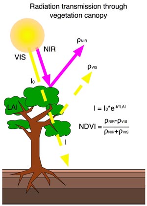
Especially satellite remote sensing methods have shown in the last two decades that land surface parameters can also be remotely estimated from space with high accuracy. Remote sensing offers the possibility to map large areas or the whole planet with a large spatial and temporal resolution, like this wouldn’t be possible by ground measurements. But in these indirect measurements new relationships between the measured quantity and the state of vegetation are needed. As it can be seen in Figure 1, healthy plants absorb light for their photsynthesis process in the visible part of the spectrum (especially red and blue) and strongly reflect light in the near-infrared part of the spectrum. Mainly, the green chlorophyl in the leaves does absorb a lot of visible light and the mesophyl cells scatter light in near-infrared wavelengths. Inactive vegetation (winter deciduous trees), dry vegetation, bare soil and snow do not show this spectral response.
Because of this spectral behavior of plants the remote sensing community created the NDVI (Normalized Difference Vegetation Index) parameter, which exploits the spectral properties of land surface vegetation:
NDVI= (NIR-VIS)/(NIR+VIS) [-] (2)
Where NIR and VIS are the near-infrared and visible reflectances of the land surface. A reflectance is calculated by dividing the outgoing (reflected) light by the incident (solar) light. Green and active vegetation does have an NDVI of 0.2-0.8, stressed vegetation, soil and snow does have NDVI values of -0.2 to 0.2. In satellite remote sensing the wavelengths in the red (NOAA AVHRR: 620-700nm) and the near-infrared (NOAA AVHRR: 740-1100nm) are commonly used to derive the NDVI.
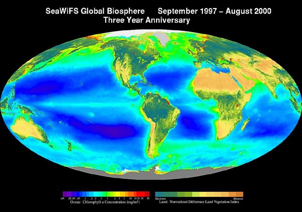
Figure 2: Global map of satellite derived NDVI (on land) and chlorophyll concentration (in the oceans) by using radiometric methods
NDVI is neither a parameter for direct use in numerical models nor can ecosystem researchers directly compare it with their ground based vegetation studies. Nevertheless, it is strongly related to the amount of radiation used by the photosynthesis process in plants. FPAR (Fraction of Photosynthetically Active Radiation absorbed by the green leaves of the canopy) can be estimated from NDVI by a linear scaling dependent on vegetation class:
FPAR=(NDVI-NDVImin)/(NDVImax-NDVImin)*(FPARmax-FPARmin)+FPARmin [-] (3)
- FPARmax: maximum FPAR (0.95)
- FPARmin: minimum FPAR (0.01)
- NDVImin: minimum NDVI for a give vegetation type (around 0)
- NDVImax: maximum NDVI for a given vegetation type (0.6-0.7)
Radiation used by the photosynthesis process decays exponentially by passing through the canopy. The higher the LAI, the less radiation will be reflected. This decay can be described by using Beer’s law:
I=I0*exp(-k*LAI) [W/m2] (4)
- I0: Incident radiation at the top of the canopy [W/m2]
- I: transmitted radiation [W/m2]
- k: canopy extinction coefficient [-]
If only the PAR (Photosynthetically Active Radiation) and the APAR (Available Photosynthetically Active Radiation) is used from the radiation, then a logarithmic relationship between FPAR and LAI can be found:
APAR=FPAR*PAR [W/m2] (5)
I/I0=(1-FPAR) [-] (6)
LAI=-1/k*ln(1-FPAR) [m2/m2] (7)
This was a very brief and simplified explanation and allows the reader to relate radiometric properties of plants qualitatively and quantitatively to their biophysical properties. For scientific use, all of the above formulations do need an in-depth calibration dependent on light conditions, solar zenith angle, vegetation type, leaf properties and other factors. A more sophisticated description of these relationships can be found in Tucker (1979), Stockli and Vidale (2003), Los (1998) and Pontailler et al. (2003).
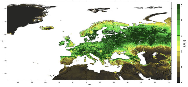
Figure 4: European LAI during a mean of July 1982-2001, derived from satellite remote sensing NDVI and FPAR
Measurement methods and examples
A. Estimation of the LAI using a pyranometer
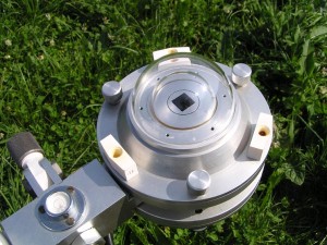
Figure 5: The pyranometer for measuring incident solar radiation (the one measuring the reflected radiation is attached underneath)
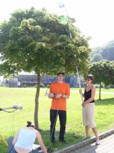
We used two pyranometers and two pyrgeometers to measure the radiation balance at the land surface. A pyranometer does measure in the shortwave (0.4-4.0um) and the pyrgeometer does measure radiation in the longwave frequencies (4.0-40.0um). Of each instrument, one is pointing upwards, measuring the top hemisphere (incident radiation) and one is pointing downwards, measuring the lower hemisphere, thus the reflected radiation.
LAI can be estimated using equation 5, and by solving it for LAI. Using this methodology, the radiation has to be measured above and under the canopy, what is only possible for trees or e.g. fully grown corn fields. Grass and other short vegetation does not allow to fit the pyranometer under the canopy. The incident radiation I0 is measured above or beneath the canopy. The transmitted radiation is measured under the canopy. It is best to take a number of measurement samples within the same canopy to get a good relationship between incident and transmitted radiation. The extinction coefficient can be estimated by using true measured LAI values (from destructive sampling). From Pontailler et al. (2003) it can be seen that k varies between 0.8 and 1.2, and a value of 1.0 should be a good choice. This method can overestimate LAI because it does not differentiate between leaves, stems and branches.
B.Estimation of LAI using hemispherical photography
The gap fraction method as described by Gower and Norman (1991) can be used to estimate LAI from hemispherical photography. We used a CI-110 (CID Inc. Vancouver USA) hemispherical camera with a 150degree viewing area. Actually, any fisheye lens can be used for this method, but the CI-110 already had the analysis software included. The hemispherical image is a grayscale image and a threshold is applied to mark the differentiation between canopy and sky. The gaps within the canopy are determined from this digital fisheye image and the transmission fractions (I/I0) are determined by zenith angle. The LAI is also determined by the Beer’s law equation. This method does also consider stems and branches as part of the canopy and can overestimate LAI. On the other side, this method will underestimate clumped foliage because it uses a threshold function between canopy and sky.
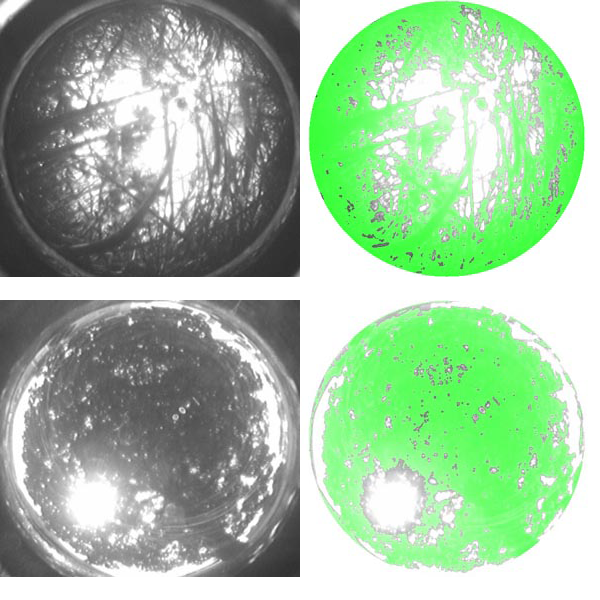
Figure 6: Hemispherical photography of grass: grayscale image (left) and the canopy threshold painted in green (right). Figure 7: Hemispherical photography of a small tree: grayscale image (left) and the canopy threshold painted in green (right)
Two examples are presented in Figure 6 and 7. In Figure 6 we have put the hemispherical camera in 20-50 cm long grass. A threshold of 50% grayscale was used. The LAI was estimated to be 1.5 at this site. The second example resulted in a LAI of 1.9. In the second example the sun is shining through the canopy in the lower left corner. This can lead to an underestimation of LAI through light scattering. Generally, overcast sky is preferrable for this method.
C.Estimating NDVI using a Radiometer
In comparison to the two previous methods NDVI only accounts for the green part of vegetation and does not measure branches and stems. A multispectral radiometer MSR16 (Cropscan Inc., Rochester USA) with 16 channels was used. Two channels were equiped with a red and near-infrared band.
We have used this equipment to determine the NDVI of a number of surfaces, including asphalt, trees, short grass, hay and tall grass. NDVI varied between 0 and 0.8 but saturated very quickly above a certain canopy thickness as this is widely known and observed. Recently, the EVI was developed, also using the blue wavelengths. From NDVI the LAI can be derived by using equations 5,6 and 7.
D. Estimating NDVI using Infrared Photography
A Radiometer like the one used in the previous example is not a common piece of equipment and very expensive to buy. Furthermore, its operation is usually not transparent to the user since the data processing of the radiometer signal requires special calibration algorithms which are hard coded in the equipment’s computer. There is a much simpler and more fun method for students to measure NDVI in the field:
Photography of visible and infrared wavelength can be used to estimate the reflectances of the two bands needed to calculate the NDVI. Infrared film and an 35mm SLR camera can be used for such an experiment. For doing both visible and infrared imagery of the same area, the film does have to be changed for every measurement. With today’s digital cameras, this experiment is even simpler. Digital cameras capture light with CCD devices that are generally sensitive to infrared wavelengths. This is actually an unwanted effect in photography since the photographic image is supposed to neither catch the UV nor the IR components of the radiation spectrum because they will mess up the colors in the image. Some professional digital cameras do therefore filter IR in their lenses, but most consumer digital cameras don’t.
We used an Olympus Camedia C-730 digital camera (Thanks very much to Eva for lending the camera during the field course) which did a perfect job for NDVI photography. We also used a Hoya R72 infrared filter, which blocks visible light below 720nm. Figure 9 shows the results of this experiment.
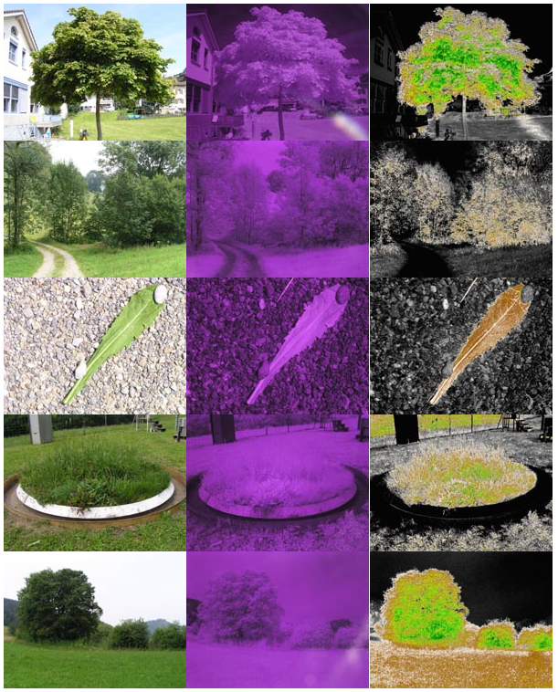
Figure 9: Examples of visible (left), infrared (center) and derived NDVI (right) measurements using a digital photo camera
All pictures were taken using a tripod and  manual settings were used, thus it is important to have a digital camera with the possibility to set manual exposure for both aperture and exposure time. Also, it essential to not move the camera between taking the infrared and the visible picture since they will then not line up anymore. A remote control would help, but was not used here. The visible radiation image can be taken using the camera’s light metering system. It is essential to achieve a good contrast in the image since vegetation shows up very dark in visible wavelengths. Usually an aperture of f5.6 to f8 was used with an ISO-100 film speed setting, resulting in an exposure time of 1/250 or lower. For the infrared image, the IR filter was manually held in front of the lens. For this kind of imagery the light metering system of the camera is unusable because only the red channel is of interest and very little light is getting through the filter. It is important to try a few speed settings (without changing the aperture setting that was used for the visible wavelength picture). I used 1s or longer exposure times to achieve good results in the IR picture. After shooting the VIS and IR images of the scene (which are my reflected radiances), the incident radiances in both wavelengths were also captured by setting the camera to a wide angle lens position and pointing it to the sky (so that the sun was included in the image). Using the same exposure settings as before two pictures (one with the IR filter and one without) were taken.
For every scene we then had four pictures. They were uploaded to a computer and a small program was written to calculate the reflectances of every wavelengths and the NDVI. From both wavelength bands only the red channel of the pictures were used. The reflectance of each wavelength was calculated by dividing the outgoing (reflected) image by the image mean of the incident (sky) picture. Reflectances range from 0.0 (totally absorbing surface) to 1.0 (perfectly reflecting surface). Then the NDVI was calculated by applying equation 2.
In Figure 9 it can be seen that vegetation has a very bright appearance in the IR. It is very contrasted to the dark color of most non-vegetated surfaces. The dandelion leaf marks a single leaf layer on top of gravel and has an NDVI value of around 0.3. The gravel appears brighter in the visible image than in the IR image. Exactly the opposite is seen for the the dandelion leaf. Trees with multiple leaf layers show NDVI of up to 0.7 like seen in the bottom row. People usually estimate the albedo of vegetation to be lower than the one of e.g. gravel or concrete. The human eye only sees wavelengths up to around 700nm and misses the high reflectivity healthy vegetation has in the near-infrared. The climatological albedo includes the wavelengths of 0.4-4.0 um and thus shows a larger value for e.g. grass (0.20-0.25) than for gravel (0.15-0.20). This experiment can be easily conducted with students by using a broadband pyranometer (Experiment A) and a narrowband radiometer (Experiment C). Furthermore LAI and could be derived from the photography NDVI using equations 5-7.
Final comments
Four methods were presented that allow to relate radiometric properties of plants to biophysical vegetation parameters widely used in climate research. Basically the same methdology is applied in satellite remote sensing applications. The most prominent satellite system performing this task is currently operated by NASA and consists of the TERRA and the AQUA spacecrafts. On both spacecrafts the MODIS (MODerate resolution Imaging Spectroradiometer) does aquire land, ocean and atmosphere data with 36 narrow spectral bands in the visible, near-infrared and infrared band. The presented methods show that broad band (using a pyranometer or hemispherical photography) and narrow band (using a radiometer or infrared photography) remote sensing methods can be used in the field to determine vegetation properties. In addition to the point measurements performed by the three first methods, the infrared photography is also able to create images (and maps if used from e.g. an airplane), which helps to evaluate the spatial heterogeneity of vegetation properties.
Dependent on equipment availability, the application of these methods in a field course can help to understand remote sensing of land surface vegetation and the experiments can motivate for further research.
References
Los, S.O., 1998, Linkages between Global Vegetation and Climate: An Analysis Based on NOAA-Advanced Very High Resolution Radiometer Data. Ph.D. Dissertation, Vrije Universiteit Amsterdam.
Gower, S. T. and Norman, J. M. (1991) Rapid estimation of leaf area index in conifer and broad-leaf plantations. Ecology, 72: 1896-1900.
Pontailler J-Y, Hymus G.J., and Drake B.G. (2003) Estimation of leaf area index using ground-based remote sensing NDVI measurements: validation and comparison with two indirect techniques. Can. J. Remote Sensing, 29 (3): 381-387.
Stockli R., and Vidale P.L., 2004, European plant phenology and climate as seen in a 20 year AVHRR land-surface parameter dataset. International Journal of Remote Sensing. 25(17), 3303–3330.
Tucker C.J. (1979) Red and photographic infrared linear combinations for monitoring vegetation. Remote Sensing of the Environment, 8: 127-150.


