
Introduction
This article is about setting up multi-projector visuals on a cylindrical screen for a flight simulator home cockpit. There are three image transformations one will need to accomplish for it to work properly.
- Transformation of the rendered content from a flat to a cylindrical projection
- Warping of the projected image to the projector – cylindrical screen geometry
- Blending of the individual projected images at their overlapping regions
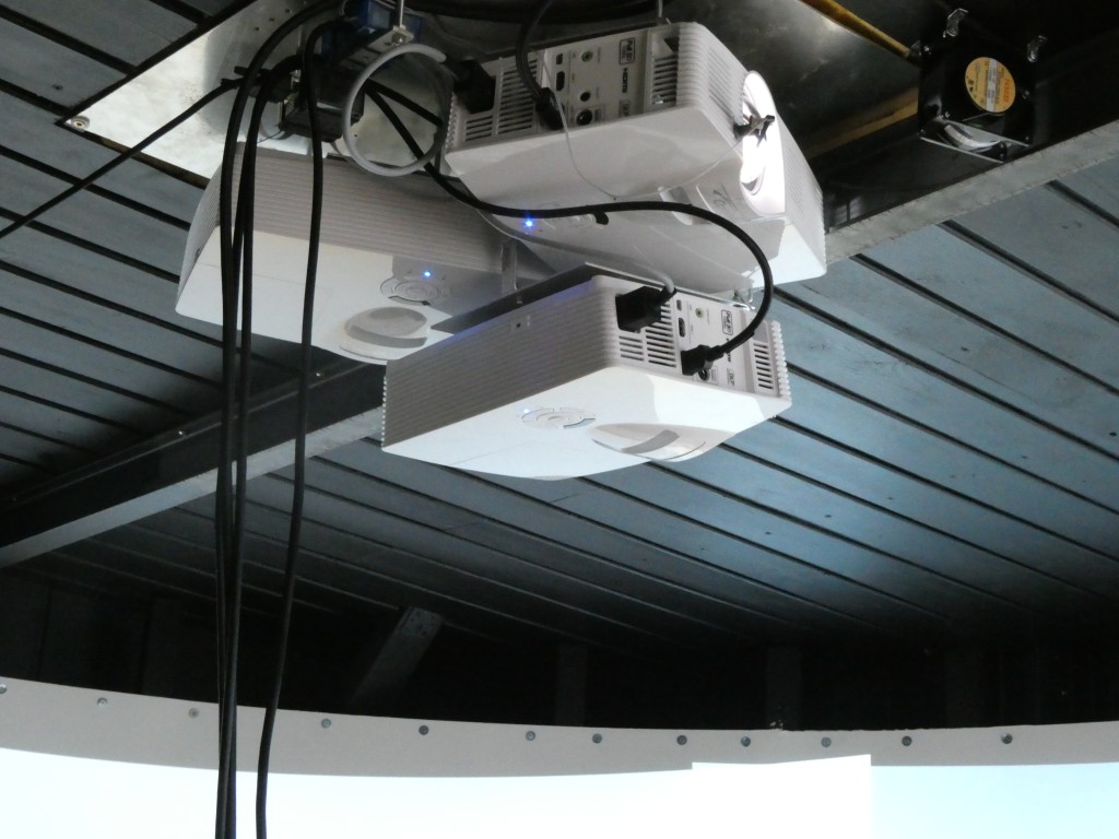
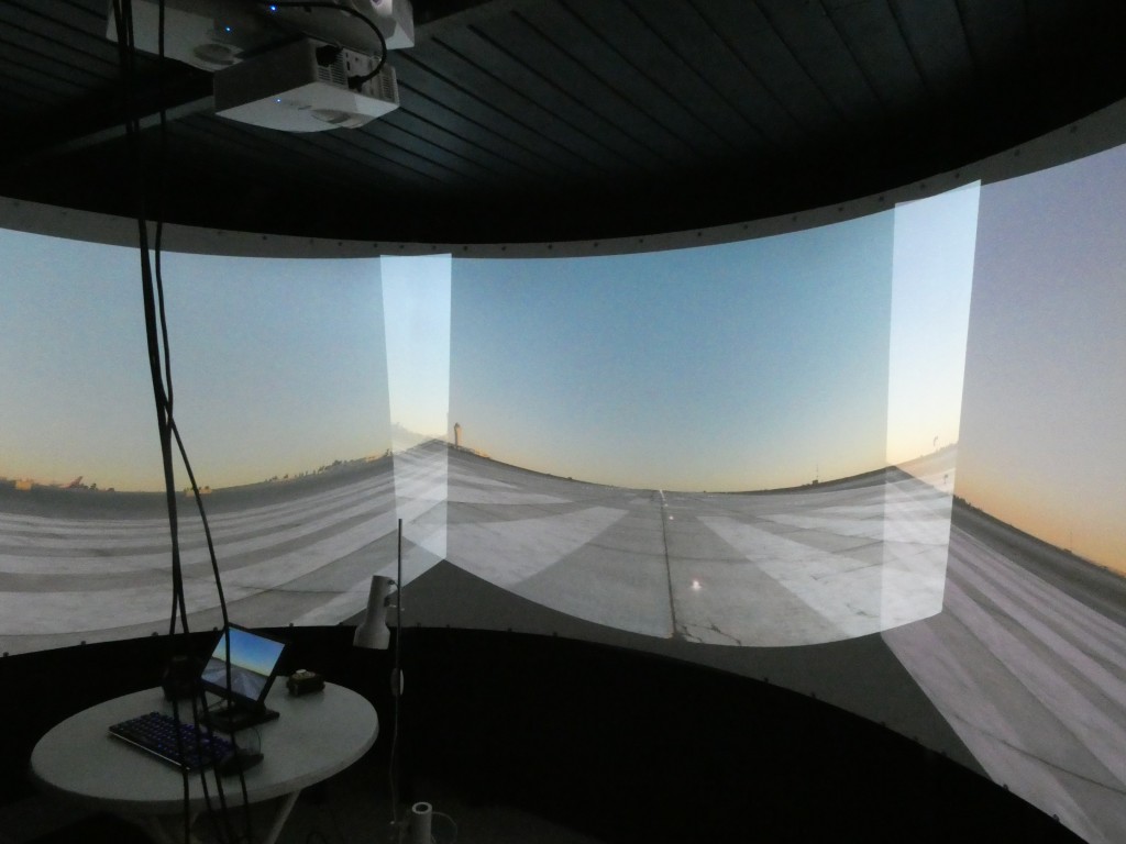
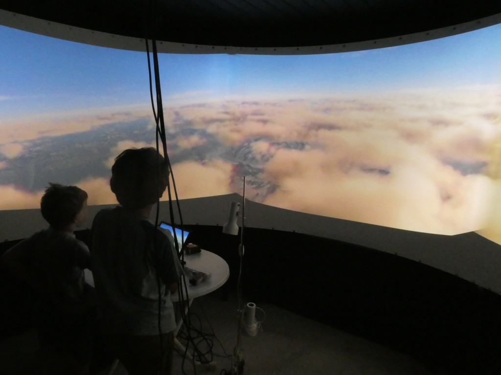
Figure 1: Sample three projector system (left). Distorted images and overlaps when projecting from X-Plane without warping & blending (center). Properly projected images on the cylindrical screen with implemented warping & blending (right).
There are several software solutions to achieve the above three steps. These are for instance, among others, Fly Elise NG, Warpalizer, Domeprojection, Vioso, Scalable Display, Digitalprojection or Pixelwix. Their price ranges from a few hundred to a few thousand US$, which is justified for the amount of sophisticated projection design, calibration and transformation features offered. Most of the software packages include manual, geometric and camera-based warping technology and are suitable driving a highly complex and professional multi-projector setup for commercial use. However, if you’re a home cockpit builder like me, these solutions are way too sophisticated. They also make you depend on yet another third party supplier, which can cause sleepless nights in case of missing updates and incompatibilities. And if you work on Linux like me, most of these solutions do not apply at all since they all require Windows as operating system.
There is a simple solution to that problem: X-Plane has steps 1 — 3 built in. No need to buy an additional software: planar – cylindrical transformation, warping to cylindrical screen and blending IS part of X-Plane. Thanks to Austin and his superb crew!
However, there are three drawbacks in X-Plane’s native support for multi-projector setups:
- Transformation from planar to cylindrical projection cuts of a substantial part of the image at image edges.
- You can only manually define the warping grid, which needs quite some fiddling with many control points and a horizontal / vertical laser calibration.
- You have to buy the PRO Version of X-Plane for around 1000 US$. This is fine for commercial users charging 100-200 US$ per hour of flight. I however build the flight simulator for my own pleasure, but still would like to run it in a highly realistic environment with multiple projectors and a curved screen.
I am now going to show how to implement warp & blend steps 1 — 3 for a cylindrical projection and overcoming the above challenges, all native on Linux (and possibly other OS’es) and free of cost. And the presented solution is 100% compatible with X-Plane’s native warping and blending. All related code is available open source on github.
0. No Warp & Blend on Three Projectors
Set up three monitors in X-Plane with a left, a center and a right view using different horizontal view angles. This would be all you need to do if using three monitors for visuals in your home cockpit.
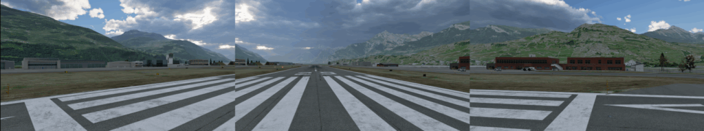
Figure 2: Pure planar projection with three view angles (left: -68 degrees, center: 0 degrees, right: +68 degrees. Note that there is some overlap for blending.
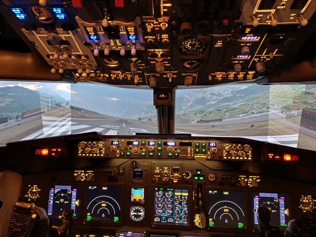
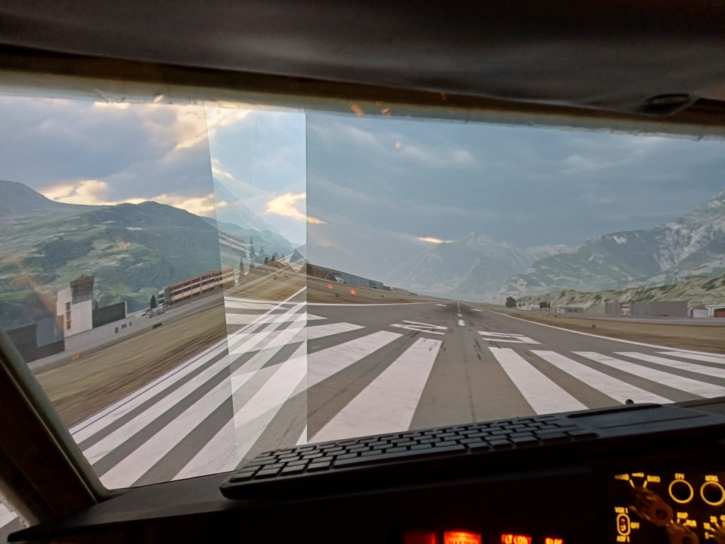
Figure 3: The planar projection looks distorted and quite ugly on a cylindrical screen as expected.
1. Transforming Rendered Content from Planar to Cylindrical Projection
The 3D content of computer games is rendered on an imaginary flat plane sitting in front of the user. Ideally this plane reflects the distance of the flat monitor from the user. This means that the horizontal and vertical Field Of Views (FOVx and FOVy) of the rendered plane and of the eye-to-monitor geometry are comparable. To cover a true 180 degree FOVx the monitor would need to be infinitely wide. This trouble can be avoided by having a cylindrical screen around you. However, it requires to reproject the image content of the planar rendering in your application into a cylindrical projection. So, if you ever buy a curved monitor and think that your game will look nicer, you simply get fooled by the monitor’s curvature. The content at the edges will simply appear closer than it really is and you might get a headache from playing. Those curved monitors would need a game that can render its content on a curved monitor. Which is not the case for any of the games I know. Except for X-Plane. And the latter is said not to be a game.
The solution to render on curved / cylindrical (or even spherical) screens is simple and applied in most panorama stitching software: it is a geometric transformation from X / Y to horizontal angle and screen height coordinates. This so-called cylinder projection is a basic geometric projection used in geographic mapping or in photography (see for instance: https://cs.brown.edu/courses/cs129/results/final/yunmiao/ https://mathworld.wolfram.com/CylindricalProjection.html
A common cylindrical projection squeezes the scenery vertically. In the X-Plane internal solution this is overcome by linearly stretching it during the planar to cylindrical projection. This still leaves unused (black) screen areas at the corners due to the planar to cylindrical projection geometry. My proposed solution is to render a slightly higher FOVy and stretch the vertical coordinates so that the reprojected rendered content entirely fills the image. Additional stretching has to be proportional to the tan() of the additional FOVy. This will in turn render unused / unseen content in the upper and lower center of the projected area but fill the corners.
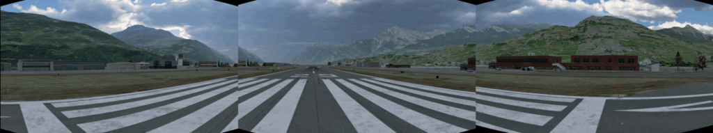
Figure 4: Transforming the rendered content from planar projection to cylindrical projection. Notice that the left and right parts of the image get compressed vertically as these objects are now physically moving to you with the curvature of the screen. The center area gets stretched vertically (and extends out of the screen) in order to maintain aspect ratio of objects.
This still looks ugly on the curved screen as the projector and cylindrical screen geometry has not yet been incorporated. So the next step is to …
2. Warping the image to the projector and cylindrical screen geometry
Now here we get to the complicated part. Projectors are built to display on a flat / planar screen mounted orthogonal in front of the projector axis.
- If you project on a cylindrical screen, pixels in the center of each projector image travel farther than they are intended on a planar screen. The image in the center becomes vertically exaggerated and distored as seen in Figure 1 center and Figure 3.
- If the projector is tilted, the so-called “keystone” effect has to be corrected. The image appears wider on the upper than on the lower border (or vice versa) and the image is squeezed vertically.
The classic way to overcome this is to set up a grid of control points and manually make these points level again with the help of a laser leveler. The laser leveler can be found in every hardware shop and will draw precise horizontal and vertical lines on your cylindrical screen. You can use it to mark a “real’ grid on you cylindrical screen, then adjust your warping grid points to this “real” grid. Let us call this the empirical warping method. This method is available in X-Plane and in most projection software solutions.
Most projection software solutions also include a camera-based warping method. A simple web cam connected to the projection software and filming the projection screen allows to auto-adjust the warping grid. This solution is usually free of trouble, but you have to buy it.
The solution that I propose here is the so-called geometric warping. It is available in some projection software solutions as well. It is based on the fact that you most likely know the size and radius of your projection screen and you also know the distance of your projectors from the screen etc:
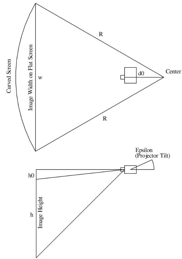
Figure 5: Basic projector and screen distances and angles
This is good news, since with the application of a few trigonometric functions we can calculate the position of each projected pixel on the cylindrical screen and in turn also correct this position for its displacement due to the projector – screen geometry. The solution is simple for projectors mounted radially from the center of the projector screen and pointing in the direction of the screen. All you have to know is:
- Radius R [cm] of cylinder forming your curved screen
- Distance d0 [cm] of focal point of projector from cylinder center point
- Height h0 [cm] of projected image above lens center point
- Throw Ratio tr [-] of your projector. This is the relationship between the distance from the projector to the screen and the width of the projected image. For short throw projectors tr < 1.0.
- Projector tilt angle epsilon [deg]
The projector – screen warping calculation is a bit more difficult for a tilted projector, but still does not exceed basic geometry stuff I have learned in college many years back.
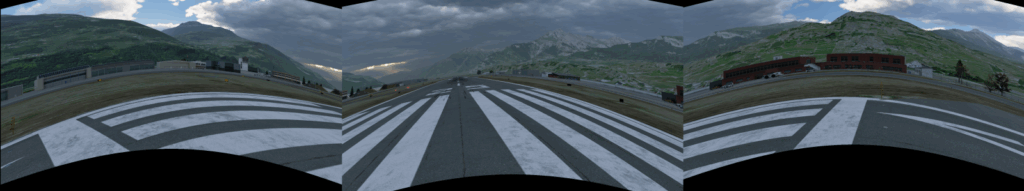
Figure 6: This are the warped left, center and right X-Plane renderings. Since the projectors are ceiling-mounted, the images are moved up towards the center in order to correct projector-screen geometry. Now this looks ugly and distorted on planar screens.
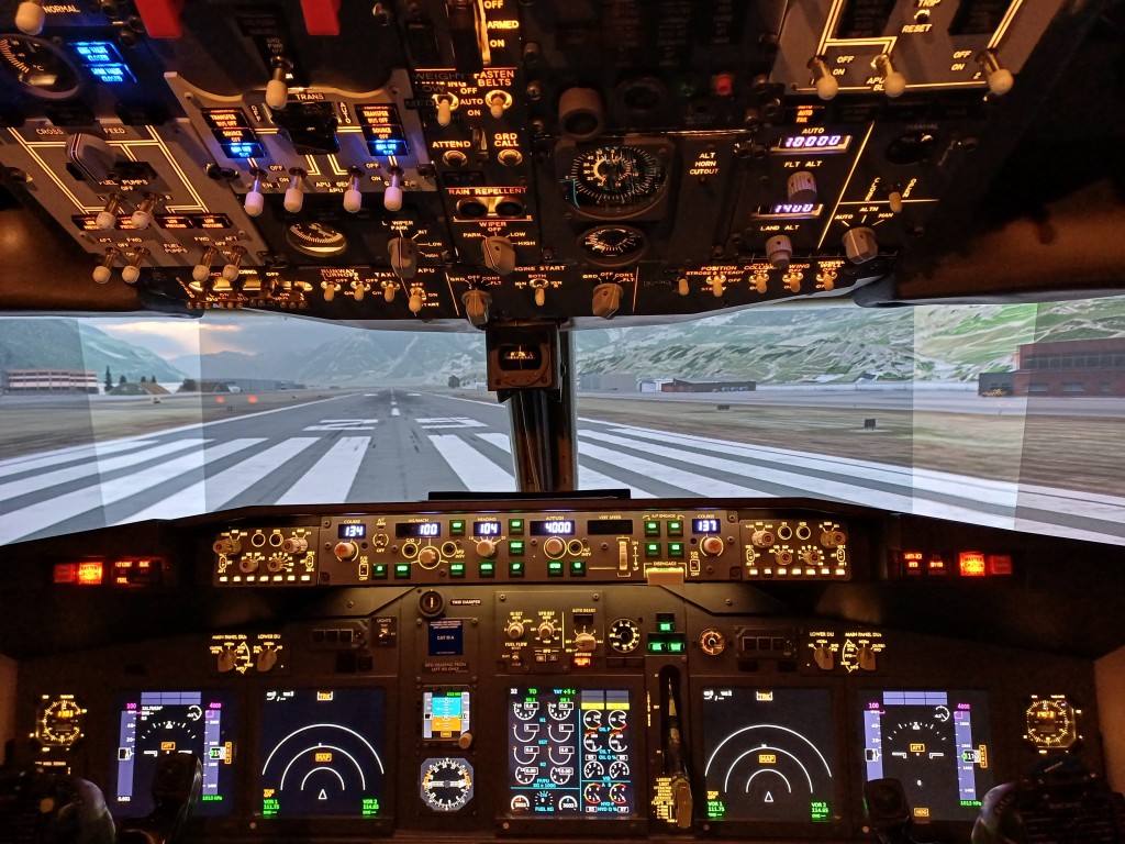
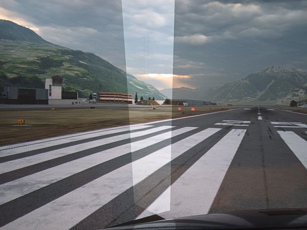
Figure 7: But magically the warping now looks quite nice on the projected cylindrical screen. The overlaps are still here. So next we have to continue with blending.
3. Blending of the individual projected images at their overlapping regions
Well, blending is not big science either. One has to control the alpha level of the projected image through the overlapping regions. It is wise to choose a non linear alpha level curve as RGB intensity values are not linearly transformed into light intensity in the projector. The so-called gamma level of projecting devices may vary. I have implemented a sigmoid function and scale them vertically around the midpoint using an exponent of 0.75 – 1.25 to account for different gamma levels.
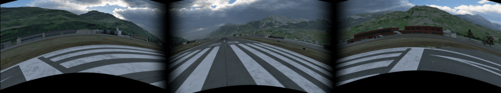
Figure 8: The warped and blended left, center and right X-Plane renderings.
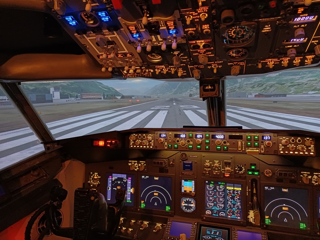
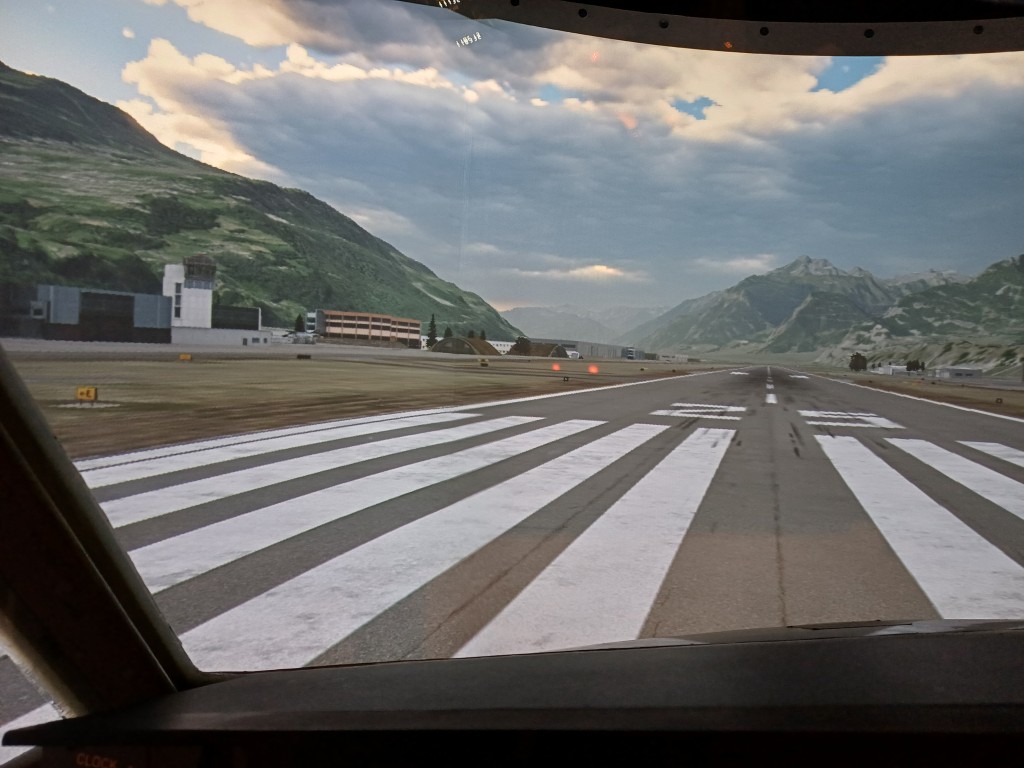
Figure 9: And now we have a complete warped and blended projection on a cylindrical screen using three projectors. Weather has become better in LSGS while writing the story. Did you notice?
4. How does it work? Can I do it myself?
YES OF COURSE! First of all: you can find the full code on my github repo.
- The python Code buildwarpblend.py (found in scripts/ of above github repo) does all the calculations and it lets you adjust projection parameters (Figure 10).
- buildwarpblend.py generates a warping grid which you can check against a laser leveler without having to start X-Plane (see Figure 11)
- You can save a X-Plane Window Preferences file and load the warp & blend grid in X-Plane
- You can alternatively save warp & blend grid file for use with the NVIDIA warp & blend API. This is read by the code warpblend.c (found in src/ of above github repo) and does the warp & blend natively on the GPU. X-Plane will just need to be initialized with the number of monitors and with the correct horizontal view angle shifts.
If you save the X-Plane Window Preference file, you will use X-Plane’s warping and blending capability and simply feed the pre-calculated warp and blend grid to X-Plane since it offers native support for warp & blend. This feature is only available in the PRO version of X-Plane. If you do not have the PRO Version, you can still test it, but you will get a warning box in the center of the screen, which will prevent you from flying with the warped and blended configuration.
If you save file for use with the NVIDIA warp & blend API, X-Plane will simply render flat monitors and the warping and blending will be done natively on your GPU. With this configuration you will not need a PRO version of X-Plane since X-Plane in the regular version is perfectly suitable for multi-monitor operation.
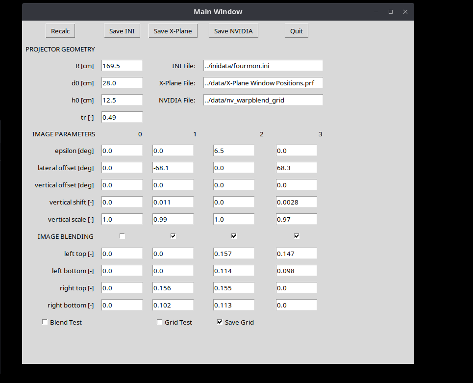
Figure 10: The warpblend.py GUI where you can modify projection parameters.
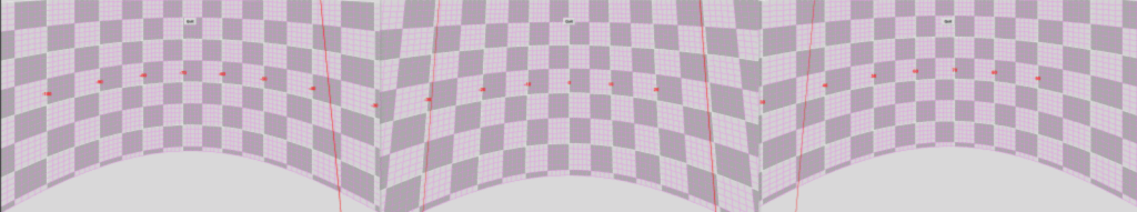
Figure 11: The warping grid as displayed on the monitors. Note that the red lines are the blend edges controlled by a top and bottom blend edge location.
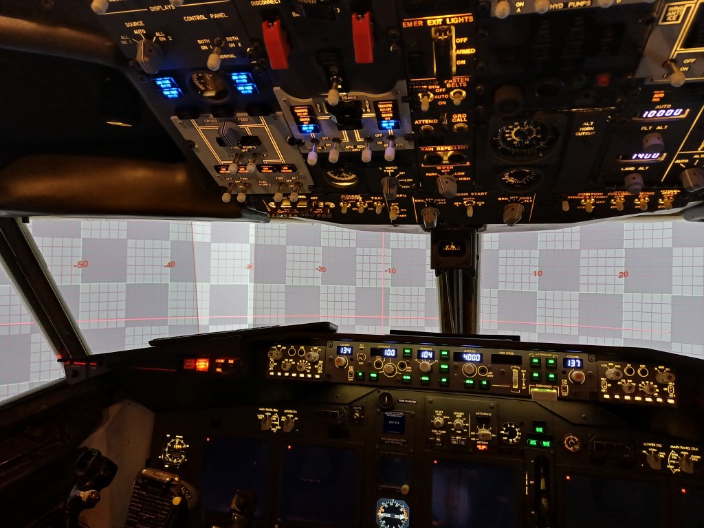
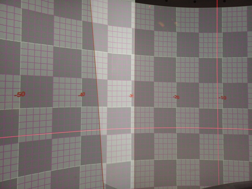
Figure 12: This is how the warping grid displays on the projected cylindrical screen. Note the red laser leveler which shows a pretty accurate geometric projection using screen and projector location only. No manual adjustment was done.
Summary
You have learned that a perfect projection warping to a cylindrical screen can be achieved without even moving a single control point by hand. Given you know the dimensions of the screen and some specifications of your projector, it can be done by use of a (relatively simple) python script to calculate corrected pixel positions for your projector (the warping grid). Blending between projected images is no big deal either (the blending grid).
Limitations:
- For this calculation projectors have to be arranged radially towards the screen, but they can be tilted.
- In case projectors are irregularly positioned anywhere in your room, the geometric correction presented here would need to be adapted (but the solution is still just geometry, after all).
- This solution is not ready for spherical screens. Anyone is welcome to extend it …
- The python script buildwarpblend.py is only tested on Linux, but the X-Plane Preference file should be valid on Windows or OSX as well
- NVIDIA warp & blend API only works on Linux and warpblend.c would need to be adapted for the NVIDIA warp & blend API on Windows
- In X-Plane under Linux, multiple monitors cannot be edited in X-Plane itself. You can however feed it the X-Plane Window Preference file and it will organize the screens accordingly. Please also check out the bash script located here on github which can be used to place X-Plane windows on the respective monitors and run them at full screen.
Unfortunately, NVIDIA has stopped to offer the warp & blend API for consumer RTX / GTX graphics cards as of driver version 570. They only continue to offer this feature for the expensive professional Quadro / RTX graphics cards. Please write to NVIDIA and ask them to re-establish the warp & blend API for all graphics cards.