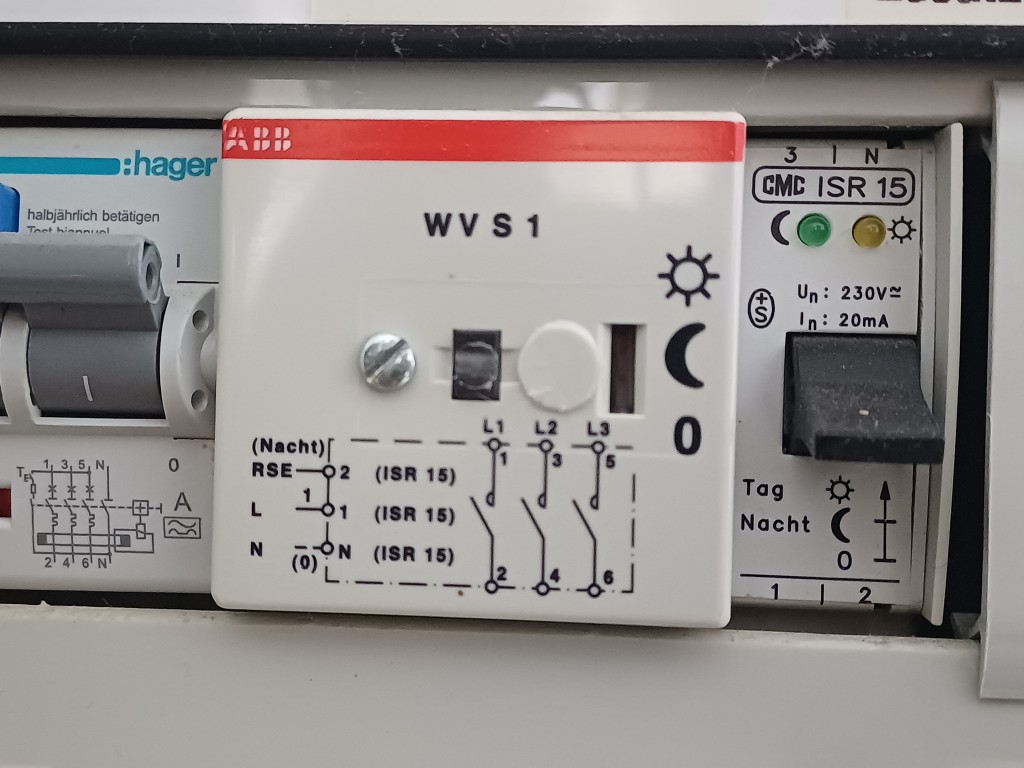
Wir besitzen einen Boiler, der im Winter von unserer Pelletsheizung und im Sommer elektrisch geheizt wird. Die elektrische Heizung wird durch den untenstehend abgebildeten Boilersteuerschütz der ABB gesteuert. Dieser Baustein reagiert auf die durch die Energie Wasser Bern (EWB) generierten Signale im Stromnetz und lädt den Boiler in der Nacht. Man kann mit dem schwarzen Taster situativ auch am Tag den Boiler laden.
Diese Steuerung ist weit verbreitet und beruht auf der Annahme, dass aufgrund der Kernenergie in der Nacht zu viel unregelbarer Bandstrom vorhanden ist. Dank dem Zubau von Solarenergie hat sich die Situation aber geändert. Wir haben in Europa und auch in der Schweiz im Sommer am Tag so viel überschüssigen Strom aus PV-Anlagen, dass dieser Strom sogar mit negativen Preisen verkauft wird (dh. der Abnehmer erhält Geld)
Ich zahle Ihnen, liebe EWB, zurzeit einen Einheitstarif von ca. 12-13 Rp./kWh und beziehe für meinen Boiler von Ihnen den Strom im Sommer in der Nacht. Genau dann, wenn Sie dafür am meisten zahlen.
Wie wäre es mit einem Deal, der zu 100% zu Ihren Gunsten liegt?
Ich bezahle Ihnen weiterhin die gewünschten 12-13 Rp./kWh und Sie ersetzen meine Boilersteuerung durch eine, bei der Sie entscheiden können, wann mein Boiler lädt. Sie könnten mit dieser Lösung sehr viel mehr Geld erwirtschaften, in dem Sie z.B. im Sommer am Mittag, wenn Sie nichts für den Strom bezahlen müssen, meinen Boiler laden würden, Die einzige Bedingung wäre, dass der Boiler mindestens einmal pro Tag auf ca. 65 Grad geheizt wird. Dasselbe könnten Sie bei zig 1000en dieser weit verbreiteten Boilersteuerungen tun.
Sie mögen jetzt entgegnen, dass mein Vorschlag für mich als Stromkunde keinen Gewinn erlaubt und daher nicht ernst gemeint sein muss. Sehen Sie, es ist mir wichtig, dass wir auch den Verbrauch möglichst rasch und effektiv an die Produktion von erneuerbaren Energien anpassen. Schlussendlich wird der Deal dann schon auch für mich Vorteile haben, nämlich als Beitrag zu einer stabilen und zukunftsfähigen Stromversorgung.
Idealerweise würde ich als Stromkunde selbst den Strom auf dem Markt einkaufen können und somit preisgesteuert den Boiler laden. Davon sind wir leider in der Schweiz aufgrund von regulatorischen Hürden noch weit entfernt. Mein Kollege aus England verdient übrigens mit seiner Solaranlage und mit der Batterie seines Elektroautos mittlerweile als privater Stromhändler mehr Geld, als er für den Strom ausgibt. Hat irgendjemand gesagt, in England regne es häufig oder die Schweizer seien so fortschrittlich?
Ich freue mich auf Ihre Antwort auf meinen Deal oder auf einen ernstgemeinten Gegenvorschlag.
Die Löhne von Bundesangestellten werden öfters von den Medien wie auch im Parlament als zu hoch erachtet. Es wird argumentiert, dass der mittlere Jahreslohn in der Privatwirtschaft bei 90’000 Fr. und beim Bund bei 131’000 Fr. liege. Somit würde die Privatwirtschaft Arbeitskräfte an den Bund verlieren. Ist es möglich, dass bei diesen Studien unreflektiert Äpfel und Birnen vermischt werden? Wie würden diese Lohnspannen aussehen, wenn in der Privatwirtschaft nur Investmentbanker und beim Bund nur Bäcker arbeiten würden? Idealerweise vergleicht man doch dieselbe Ausbildung, Berufserfahrung und Funktion und findet dann branchen-, gender- oder ausbildungsspezifische Unterschiede.
Ich kann euch hier nachvollziehbar ein durchaus amüsantes wie auch reelles Beispiel geben, wie die obenstehenden Unterschiede auch zu ungunsten der Privatwirtschaft ausfallen können.
Ich arbeitete von 2008 – 2022 beim Bundesamt für Meteorologie und Klimatologie MeteoSchweiz als Fernerkundungsspezialist und später als Teamleiter. Ich besitze den Doktortitel in Naturwissenschaften der ETH, habe ca. 10 Jahre bei der NASA und drei Jahre in der Forschung gearbeitet. Der Maximal-Bruttolohn, der die MeteoSchweiz in der Lohnklasse 23 ausbezahlt, ist laut transparenter Lohntabelle des Bundes ca. 150’000 Fr. pro Jahr. Das ergibt bei 230 Arbeitstagen pro Jahr und 8.4h Arbeitszeit ein Lohn von 77 Fr. pro Stunde. Da die MeteoSchweiz auch als kostenneutraler Dienstleister agiert, wurde meine Dienstleistung zu einem Stundenansatz von 165 Fr. berechnet (Siehe Verordnung über die Meteorologie und Klimatologie Art. 8). In diesem Ansatz sind Infrastrukturkosten und personeller Overhead enthalten.
Ein Bundesamt zahlt dem Fachspezialisten ein Stundenlohn von 77 Fr. bei einem Vollkostentarif von 165 Fr.
Mein Sohn war vor zwei Jahren bei einem Kieferorthopäden. Der Kieferorthopäde besitzt einen Doktortitel, einige Jahre an Berufserfahrung und leitet ein Team von einigen Personen und führt eine Praxis. Auch wenn die Ausbildungen zwischen Kieferorthopäden und Fernerkundungsspezialist nicht komplett vergleichbar sind, dauern sie etwa gleichlang und die eigentliche Berufsarbeit erfordert jahrelanges Training und Spezialisierung nach Abschluss der Ausbildung. Teamleitung und Geschäftsführung sind analog zu betrachten.
Wir bekamen nach den ersten beiden Konsultationen vom Kieferorthopäden die erste Honorarrechnung über 1376 Fr. Die beiden Konsultationen dauerten insgesamt etwa eine Stunde und ich gehe davon aus, dass der Kieferorthopäde für den dreiseitigen Analysebericht, der vorwiegend aus Textbausteinen und den gemachten Fotos / 3D Scans bestand, noch maximal eine weitere Stunde Aufwand gehabt hat. Der Stundenansatz des Kieferorthopäden beträgt somit minimal 680 Fr. Er muss davon noch seine Angestellten und die Praxisausrüstung bezahlen. Bleiben wir beim selben Rechnungsmix wie beim Bundesamt und halbieren den Vollkostenansatz, um auf den Lohn des Kieferorthopäden zu kommen: 340 Fr. pro Stunde
Der Kieferorthopäde bezahlt sich einen Stundenlohn von geschätzt 340 Fr. bei einem Vollkostentarif von 680 Fr.
Ist das nicht abgefahren? Ich schrieb dem Kieferorthopäden in der Folge eine E-mail und er erklärte mir ausführlich seine Tarifbestimmungen und gab an, dass er mit dem Taxpunkt-Ansatz von 1.0 der günstigste Kieferorthopäde sei. Ich verstand als Bundesangestellter, der sehr wohl honoriert, was er verdient, die Welt nicht mehr …
Der Stundenlohn des Kieferorthopäden ist ca. 4.5 mal höher als die des Bundesangestellten mit ähnlicher Ausbildung und Spezialisierung.
Man mag jetzt entgegnen, der Kieferorthopäde habe eine extravagante Praxis mit teuren Instrumenten und teuren Mitarbeitenden. Ich kann dazu nichts sagen, denn Praxisausrüstung ist nicht mein Spezialgebiet. Ich kann einzig sagen, dass mein früherer Arbeitgeber MeteoSchweiz fünf Standorte, mehrere Supercomputing-Zentren, teure Radaranlagen sowie 200 Messstationen gebaut und betrieben hat. Das führt zu relativ hohen Sachkosten. Ich gehe darum nicht davon aus, dass die standardisierte Praxisinneneinrichtung eines Kieferorthopäden die einer hochalpinen Radaranlage übertreffen wird und erachte die oben gemachte Aufteilung der Vollkosten, Sachkosten und Stundenlohn beim Kieferorthopäden als valide.
Man mag jetzt auch entgegnen, dass die Behandlung von gesundheitlichen Beschwerden von der Gesellschaft als wertvoller erachtet wird als die Klimabeobachtung aus dem Weltall und folgedessen (marktwirtschaftlich) mehr dafür bezahlt werden sollte. Fair enough. Dann würde ich aber gerne folgendes motivieren:
Der Stundenlohn von Pflegefachpersonen mit 10-jähriger Arbeitserfahrung beträgt leider lediglich 45 Fr. Diese leisten tatsächlich einen wertvollen Beitrag zur Behandlung von gesundheitlichen Beschwerden der Gesellschaft und sollten entlang dieser Gedanken auch um ein Mehrfaches des Bundesangestellten erhalten.
Weitere Argumente, warum der Stundenansatz des Kieferorthopäden die des Bundesangestellten in gleicher Funktion um das viereinhalbfache übersteigen sollte, nehme ich gerne entgegen …
This article is about setting up multi-projector visuals on a cylindrical screen for a flight simulator home cockpit. There are three image transformations one will need to accomplish for it to work properly.
Transformation of the rendered content from a flat to a cylindrical projection
Warping of the projected image to the projector – cylindrical screen geometry
Blending of the individual projected images at their overlapping regions
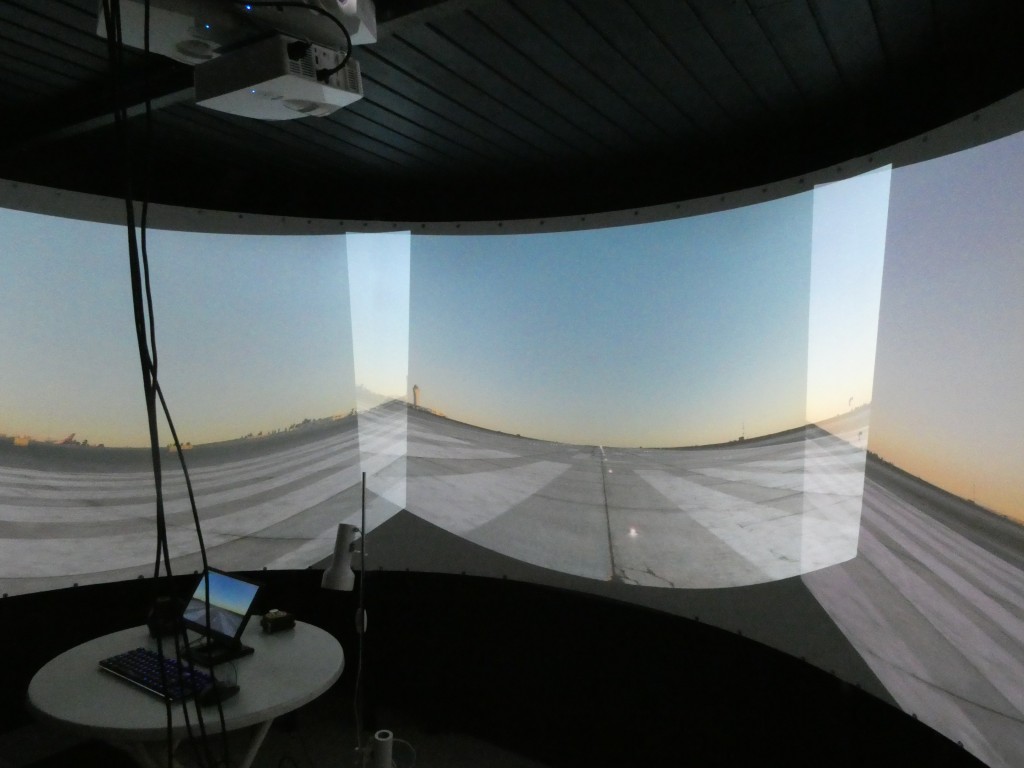
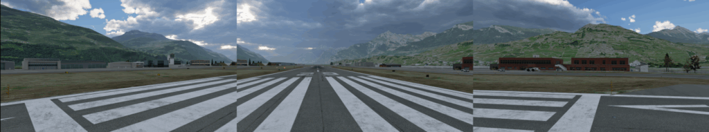
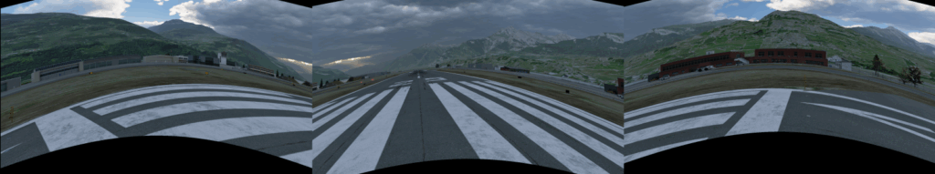
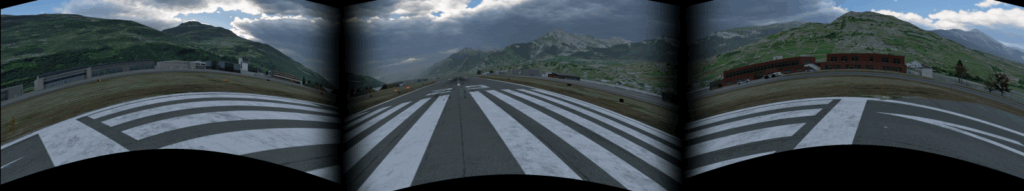
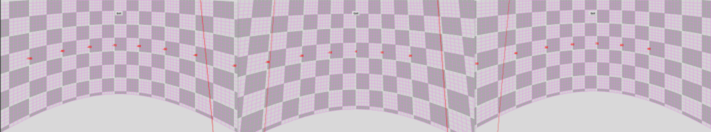
Figure 1: Sample three projector system (left). Distorted images and overlaps when projecting from X-Plane without warping & blending (center). Properly projected images on the cylindrical screen with implemented warping & blending (right).
There are several software solutions to achieve the above three steps. These are for instance, among others, Fly Elise NG, Warpalizer, Domeprojection, Vioso, Scalable Display, Digitalprojection or Pixelwix. Their price ranges from a few hundred to a few thousand US$, which is justified for the amount of sophisticated projection design, calibration and transformation features offered. Most of the software packages include manual, geometric and camera-based warping technology and are suitable driving a highly complex and professional multi-projector setup for commercial use. However, if you’re a home cockpit builder like me, these solutions are way too sophisticated. They also make you depend on yet another third party supplier, which can cause sleepless nights in case of missing updates and incompatibilities. And if you work on Linux like me, most of these solutions do not apply at all since they all require Windows as operating system.
There is a simple solution to that problem: X-Plane has steps 1 — 3 built in. No need to buy an additional software: planar – cylindrical transformation, warping to cylindrical screen and blending IS part of X-Plane. Thanks to Austin and his superb crew!
However, there are three drawbacks in X-Plane’s native support for multi-projector setups:
Transformation from planar to cylindrical projection cuts of a substantial part of the image at image edges.
You can only manually define the warping grid, which needs quite some fiddling with many control points and a horizontal / vertical laser calibration.
You have to buy the PRO Version of X-Plane for around 1000 US$. This is fine for commercial users charging 100-200 US$ per hour of flight. I however build the flight simulator for my own pleasure, but still would like to run it in a highly realistic environment with multiple projectors and a curved screen.
I am now going to show how to implement warp & blend steps 1 — 3 for a cylindrical projection and overcoming the above challenges, all native on Linux (and possibly other OS’es) and free of cost. And the presented solution is 100% compatible with X-Plane’s native warping and blending. All related code is available open source on github.
0. No Warp & Blend on Three Projectors
Set up three monitors in X-Plane with a left, a center and a right view using different horizontal view angles. This would be all you need to do if using three monitors for visuals in your home cockpit.
Figure 2: Pure planar projection with three view angles (left: -68 degrees, center: 0 degrees, right: +68 degrees. Note that there is some overlap for blending.
Figure 3: The planar projection looks distorted and quite ugly on a cylindrical screen as expected.
1. Transforming Rendered Content from Planar to Cylindrical Projection
The 3D content of computer games is rendered on an imaginary flat plane sitting in front of the user. Ideally this plane reflects the distance of the flat monitor from the user. This means that the horizontal and vertical Field Of Views (FOVx and FOVy) of the rendered plane and of the eye-to-monitor geometry are comparable. To cover a true 180 degree FOVx the monitor would need to be infinitely wide. This trouble can be avoided by having a cylindrical screen around you. However, it requires to reproject the image content of the planar rendering in your application into a cylindrical projection. So, if you ever buy a curved monitor and think that your game will look nicer, you simply get fooled by the monitor’s curvature. The content at the edges will simply appear closer than it really is and you might get a headache from playing. Those curved monitors would need a game that can render its content on a curved monitor. Which is not the case for any of the games I know. Except for X-Plane. And the latter is said not to be a game.
The solution to render on curved / cylindrical (or even spherical) screens is simple and applied in most panorama stitching software: it is a geometric transformation from X / Y to horizontal angle and screen height coordinates. This so-called cylinder projection is a basic geometric projection used in geographic mapping or in photography (see for instance: https://cs.brown.edu/courses/cs129/results/final/yunmiao/https://mathworld.wolfram.com/CylindricalProjection.html
A common cylindrical projection squeezes the scenery vertically. In the X-Plane internal solution this is overcome by linearly stretching it during the planar to cylindrical projection. This still leaves unused (black) screen areas at the corners due to the planar to cylindrical projection geometry. My proposed solution is to render a slightly higher FOVy and stretch the vertical coordinates so that the reprojected rendered content entirely fills the image. Additional stretching has to be proportional to the tan() of the additional FOVy. This will in turn render unused / unseen content in the upper and lower center of the projected area but fill the corners.
Figure 4: Transforming the rendered content from planar projection to cylindrical projection. Notice that the left and right parts of the image get compressed vertically as these objects are now physically moving to you with the curvature of the screen. The center area gets stretched vertically (and extends out of the screen) in order to maintain aspect ratio of objects.
This still looks ugly on the curved screen as the projector and cylindrical screen geometry has not yet been incorporated. So the next step is to …
2. Warping the image to the projector and cylindrical screen geometry
Now here we get to the complicated part. Projectors are built to display on a flat / planar screen mounted orthogonal in front of the projector axis.
If you project on a cylindrical screen, pixels in the center of each projector image travel farther than they are intended on a planar screen. The image in the center becomes vertically exaggerated and distored as seen in Figure 1 center and Figure 3.
If the projector is tilted, the so-called “keystone” effect has to be corrected. The image appears wider on the upper than on the lower border (or vice versa) and the image is squeezed vertically.
The classic way to overcome this is to set up a grid of control points and manually make these points level again with the help of a laser leveler. The laser leveler can be found in every hardware shop and will draw precise horizontal and vertical lines on your cylindrical screen. You can use it to mark a “real’ grid on you cylindrical screen, then adjust your warping grid points to this “real” grid. Let us call this the empirical warping method. This method is available in X-Plane and in most projection software solutions.
Most projection software solutions also include a camera-based warping method. A simple web cam connected to the projection software and filming the projection screen allows to auto-adjust the warping grid. This solution is usually free of trouble, but you have to buy it.
The solution that I propose here is the so-called geometric warping. It is available in some projection software solutions as well. It is based on the fact that you most likely know the size and radius of your projection screen and you also know the distance of your projectors from the screen etc:
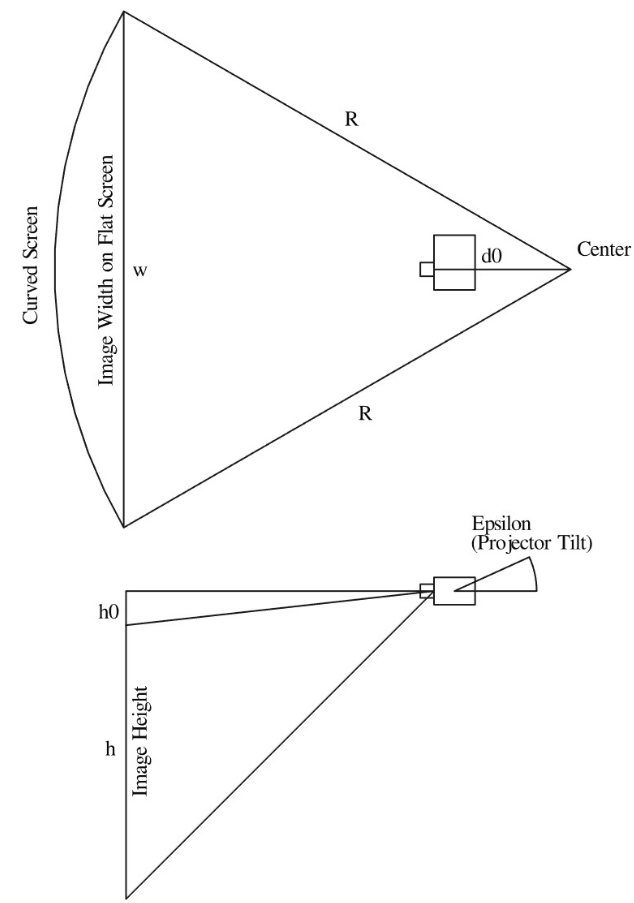
Figure 5: Basic projector and screen distances and angles
This is good news, since with the application of a few trigonometric functions we can calculate the position of each projected pixel on the cylindrical screen and in turn also correct this position for its displacement due to the projector – screen geometry. The solution is simple for projectors mounted radially from the center of the projector screen and pointing in the direction of the screen. All you have to know is:
Radius R [cm] of cylinder forming your curved screen
Distance d0 [cm] of focal point of projector from cylinder center point
Height h0 [cm] of projected image above lens center point
Throw Ratio tr [-] of your projector. This is the relationship between the distance from the projector to the screen and the width of the projected image. For short throw projectors tr < 1.0.
Projector tilt angle epsilon [deg]
The projector – screen warping calculation is a bit more difficult for a tilted projector, but still does not exceed basic geometry stuff I have learned in college many years back.
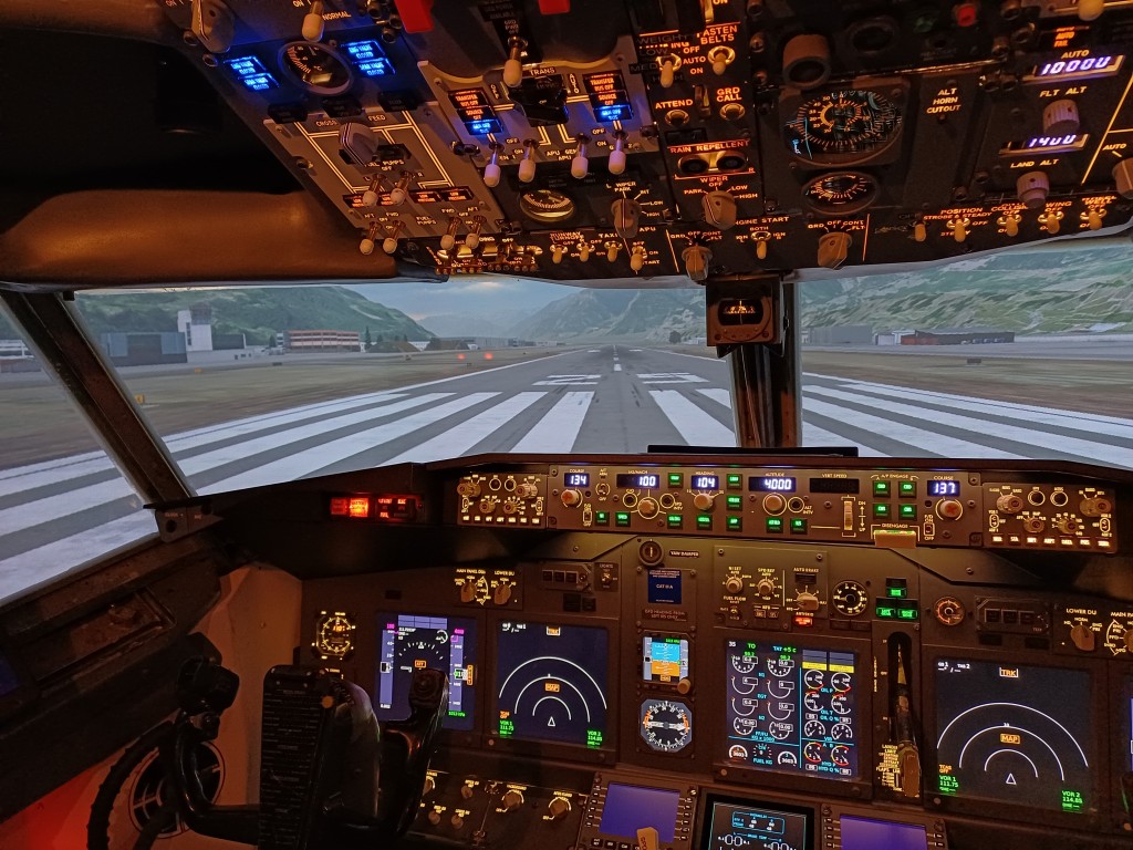
Figure 6: This are the warped left, center and right X-Plane renderings. Since the projectors are ceiling-mounted, the images are moved up towards the center in order to correct projector-screen geometry. Now this looks ugly and distorted on planar screens.
Figure 7: But magically the warping now looks quite nice on the projected cylindrical screen. The overlaps are still here. So next we have to continue with blending.
3. Blending of the individual projected images at their overlapping regions
Well, blending is not big science either. One has to control the alpha level of the projected image through the overlapping regions. It is wise to choose a non linear alpha level curve as RGB intensity values are not linearly transformed into light intensity in the projector. The so-called gamma level of projecting devices may vary. I have implemented a sigmoid function and scale them vertically around the midpoint using an exponent of 0.75 – 1.25 to account for different gamma levels.
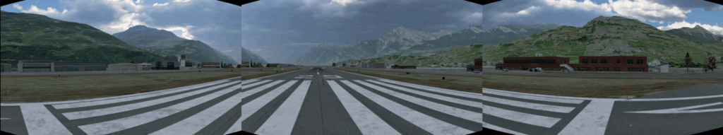
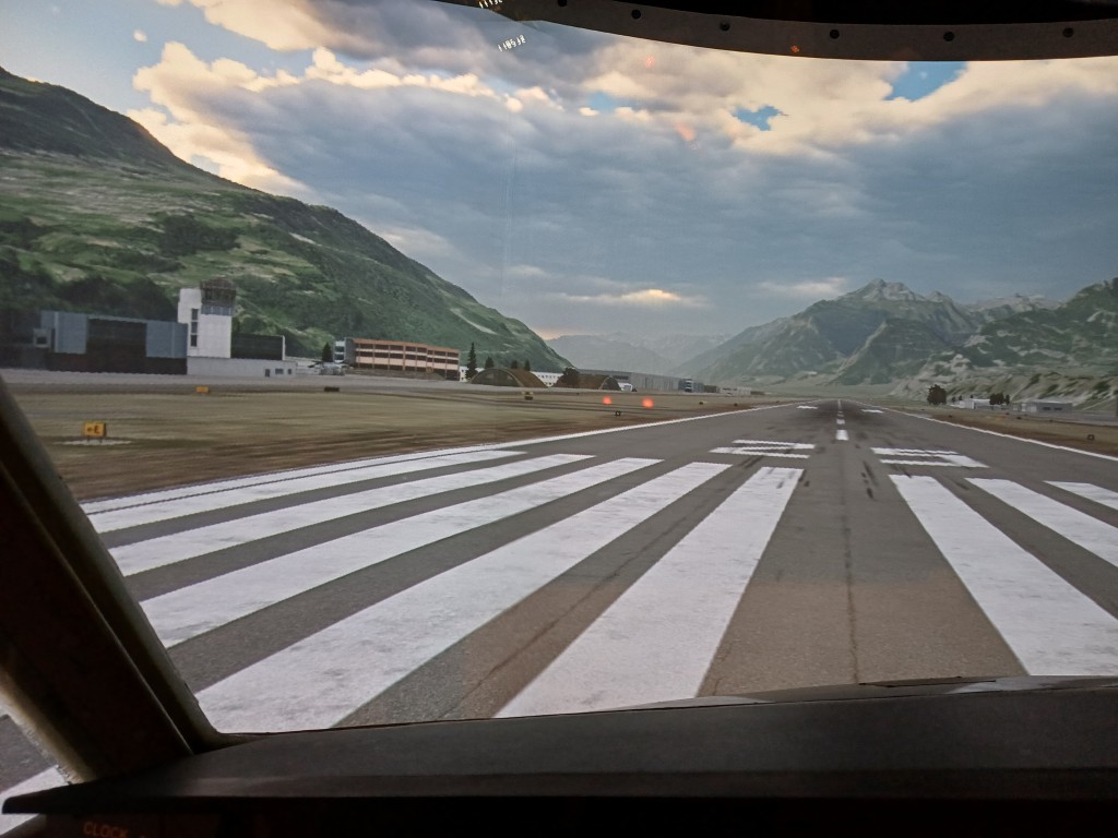
Figure 8: The warped and blended left, center and right X-Plane renderings.
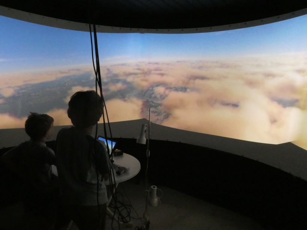
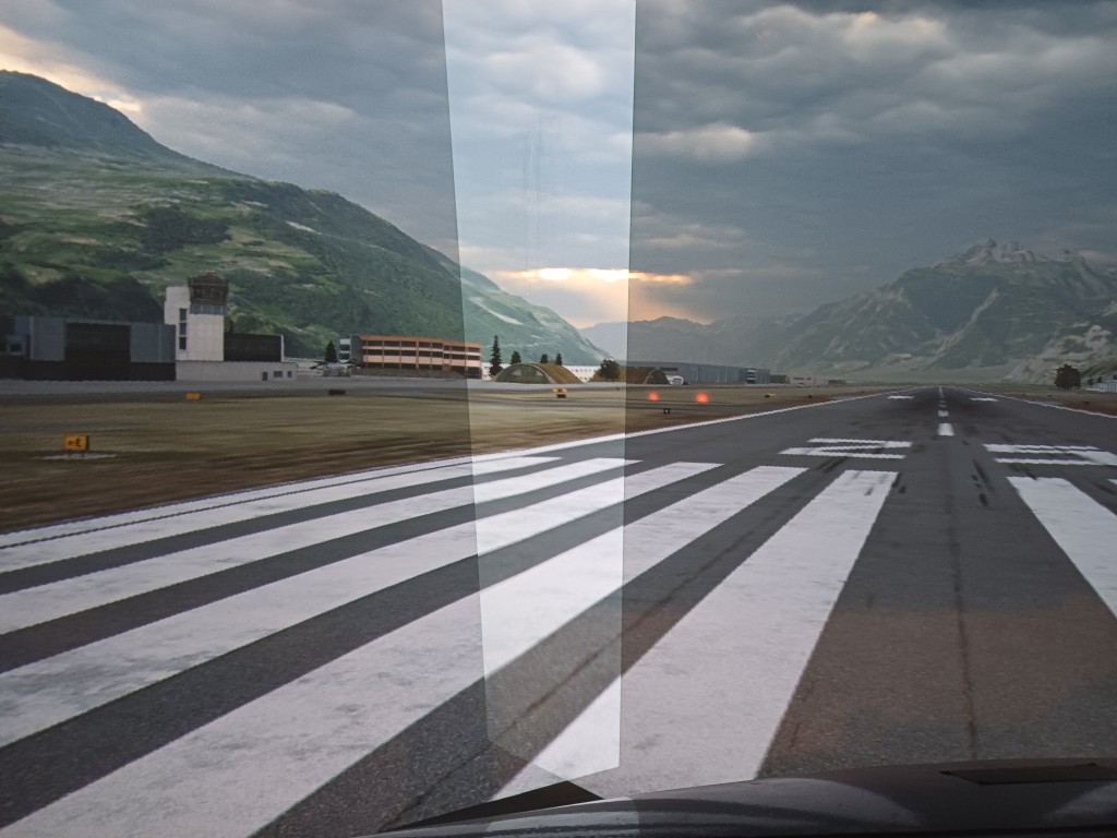
Figure 9: And now we have a complete warped and blended projection on a cylindrical screen using three projectors. Weather has become better in LSGS while writing the story. Did you notice?
4. How does it work? Can I do it myself?
YES OF COURSE! First of all: you can find the full code on my github repo.
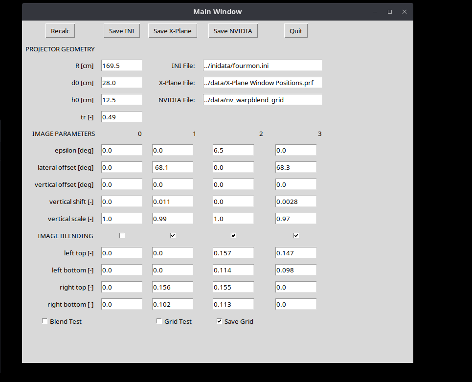
The python Code buildwarpblend.py (found in scripts/ of above github repo) does all the calculations and it lets you adjust projection parameters (Figure 10).
buildwarpblend.py generates a warping grid which you can check against a laser leveler without having to start X-Plane (see Figure 11)
You can save a X-Plane Window Preferences file and load the warp & blend grid in X-Plane
You can alternatively save warp & blend grid file for use with the NVIDIA warp & blend API. This is read by the code warpblend.c (found in src/ of above github repo) and does the warp & blend natively on the GPU. X-Plane will just need to be initialized with the number of monitors and with the correct horizontal view angle shifts.
If you save the X-Plane Window Preference file, you will use X-Plane’s warping and blending capability and simply feed the pre-calculated warp and blend grid to X-Plane since it offers native support for warp & blend. This feature is only available in the PRO version of X-Plane. If you do not have the PRO Version, you can still test it, but you will get a warning box in the center of the screen, which will prevent you from flying with the warped and blended configuration.
If you save file for use with the NVIDIA warp & blend API, X-Plane will simply render flat monitors and the warping and blending will be done natively on your GPU. With this configuration you will not need a PRO version of X-Plane since X-Plane in the regular version is perfectly suitable for multi-monitor operation.
Figure 10: The warpblend.py GUI where you can modify projection parameters.
Figure 11: The warping grid as displayed on the monitors. Note that the red lines are the blend edges controlled by a top and bottom blend edge location.
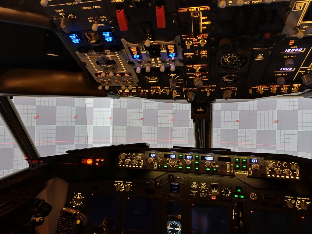
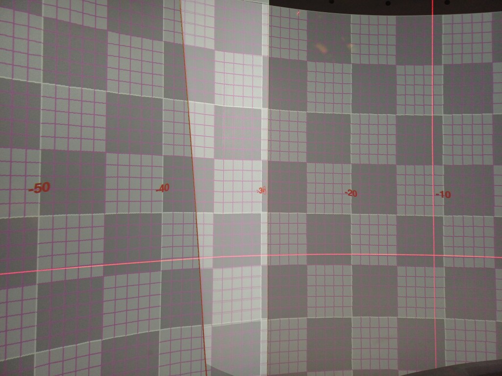
Figure 12: This is how the warping grid displays on the projected cylindrical screen. Note the red laser leveler which shows a pretty accurate geometric projection using screen and projector location only. No manual adjustment was done.
Summary
You have learned that a perfect projection warping to a cylindrical screen can be achieved without even moving a single control point by hand. Given you know the dimensions of the screen and some specifications of your projector, it can be done by use of a (relatively simple) python script to calculate corrected pixel positions for your projector (the warping grid). Blending between projected images is no big deal either (the blending grid).
Limitations:
For this calculation projectors have to be arranged radially towards the screen, but they can be tilted.
In case projectors are irregularly positioned anywhere in your room, the geometric correction presented here would need to be adapted (but the solution is still just geometry, after all).
This solution is not ready for spherical screens. Anyone is welcome to extend it …
The python script buildwarpblend.py is only tested on Linux, but the X-Plane Preference file should be valid on Windows or OSX as well
NVIDIA warp & blend API only works on Linux and warpblend.c would need to be adapted for the NVIDIA warp & blend API on Windows
In X-Plane under Linux, multiple monitors cannot be edited in X-Plane itself. You can however feed it the X-Plane Window Preference file and it will organize the screens accordingly. Please also check out the bash script located here on github which can be used to place X-Plane windows on the respective monitors and run them at full screen.
Unfortunately, NVIDIA has stopped to offer the warp & blend API for consumer RTX / GTX graphics cards as of driver version 570. They only continue to offer this feature for the expensive professional Quadro / RTX graphics cards. Please write to NVIDIA and ask them to re-establish the warp & blend API for all graphics cards.
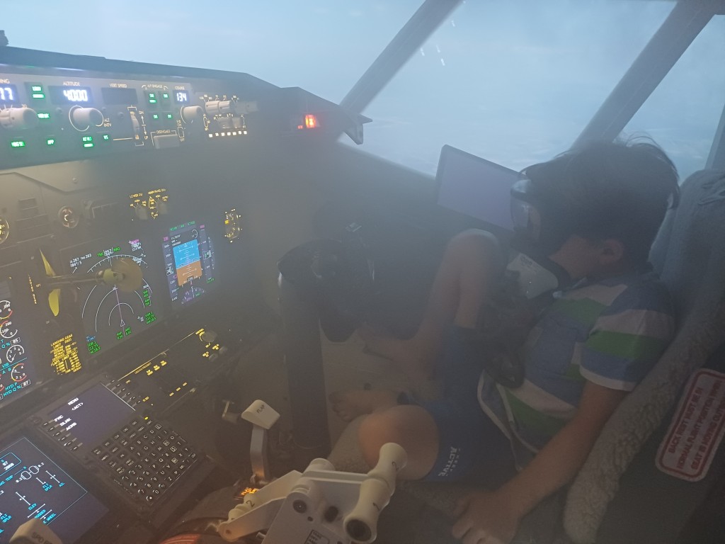
After finalizing an almost complete Boeing 737 Flight Simulator, I thought about going one step forward and trying to simulate emergency situations. Smoke in the Cockpit is one of them, and not a funny one (See for instance the fatal Swissair SR111 Accident, where a fire with the flight entertainment system generated heavy smoke and fire in the cockpit, led to many system failures and eventually rendered the plane uncontrollable)
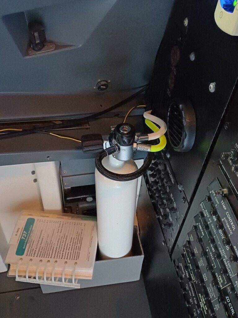
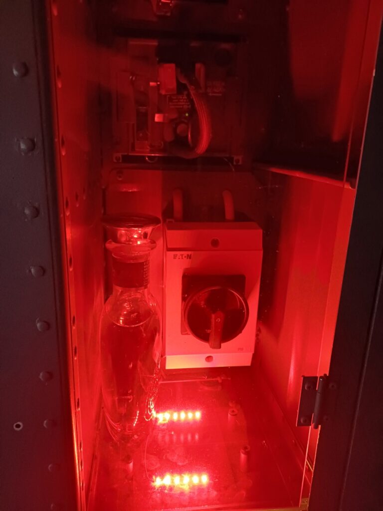
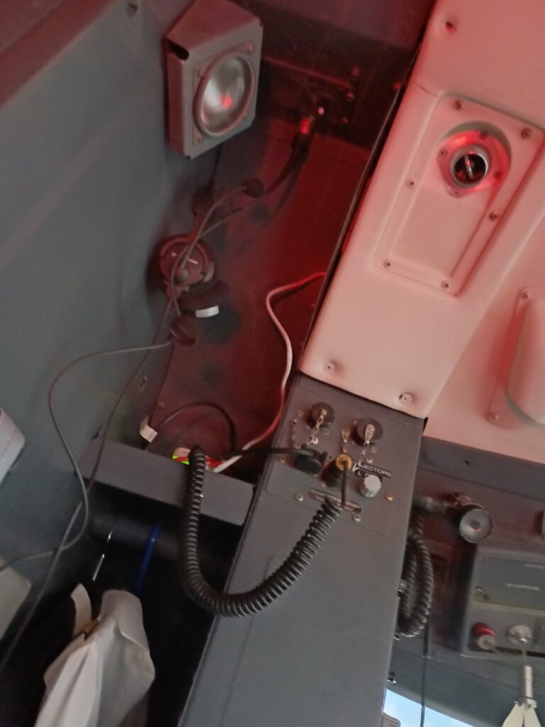
I already had three original EROS oxygen masks, so next thing was to make them operational. The first idea was to buy an air compressor and distribute compressed air among the three masks. However, air compressors distributing breathing air (instead of e.g. supplying paint brush equipment) needs to be free of oil and would not simply fit inside the cockpit itself. A friend of mine pointed out to a much simpler solution: how about using a common diving air bottle with compressed air inside?
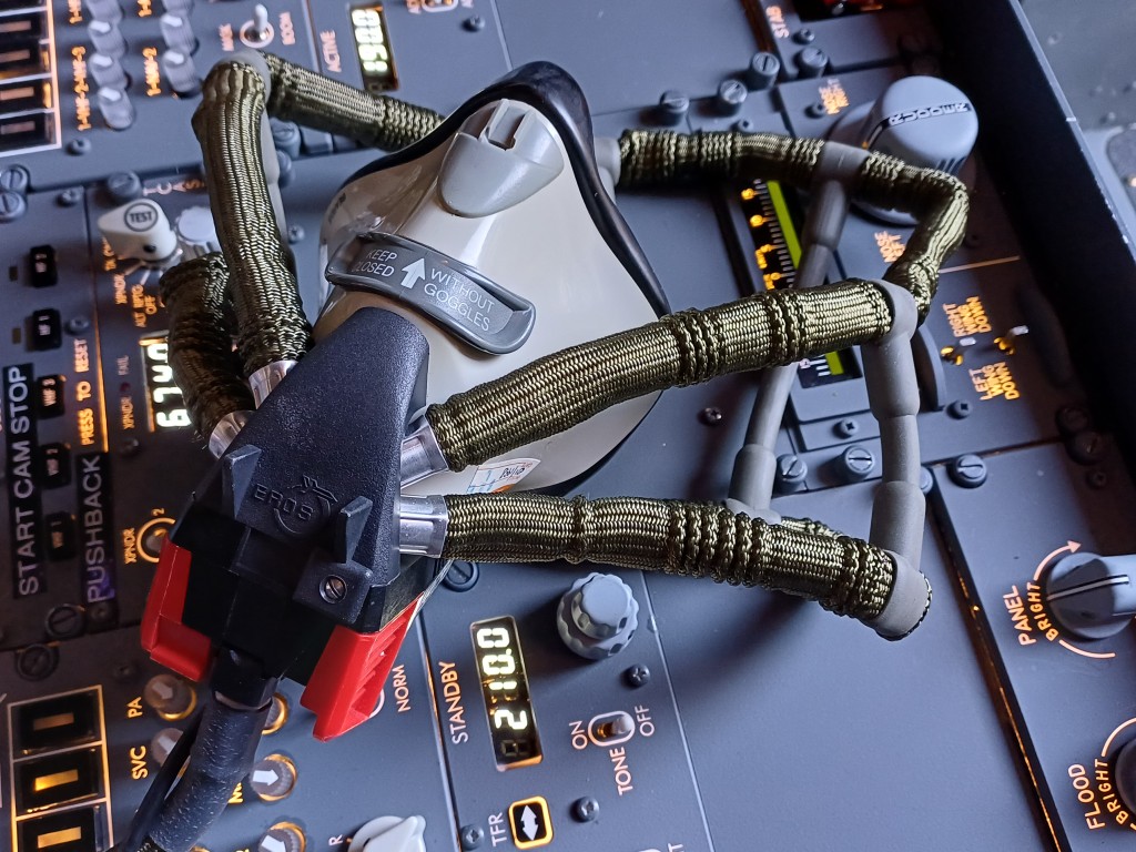
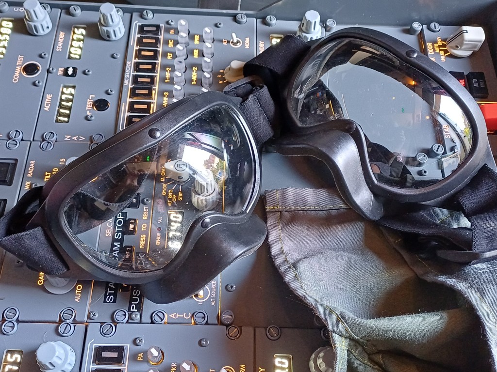
That solution actually worked, thanks to the friendly crew of the Tauchsport Käser AG (TSK) in Bern, which by coincidence sits quite close to my home. I now have a regular diving air bottle filled with regular air at 200 bar pressure, a first stage distributor, which regulates the pressure to 4.5 bar and three customized air pipes supplying the three EROS oxygen masks. The diving bottle fits well in the first officer corner of the cockpit and can be easily recharged at the TSK diving shop. The two original EROS smoke goggles also come in handy, of course. The air in the bottle should last for around 30 minutes if three people use their mask in regular (non-emergency) mode.
From left to right: Diving air bottle and pressure regulator, EROS oxygen mask, EROS smoke goggles
After fixing one last air leak at the oxygen mask container, a few minutes breathing through the mask demonstrated, that the setup works as expected. Now, let’s do the emergency situation simulation …
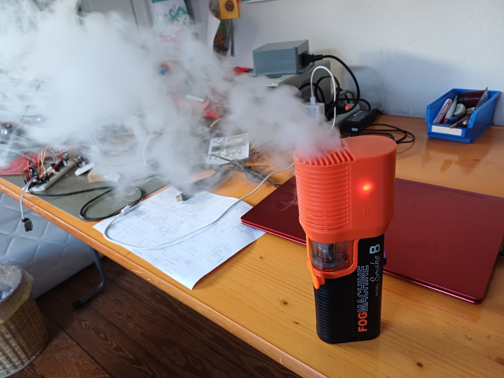
WAIT: Where is the smoke?`Here …
This is the little handheld smoke machine Lensgo Smoke B, actually intended for movie sets or smoky caipirinhas, but it is well able to fill a Boeing 737 cockpit in a few minutes.
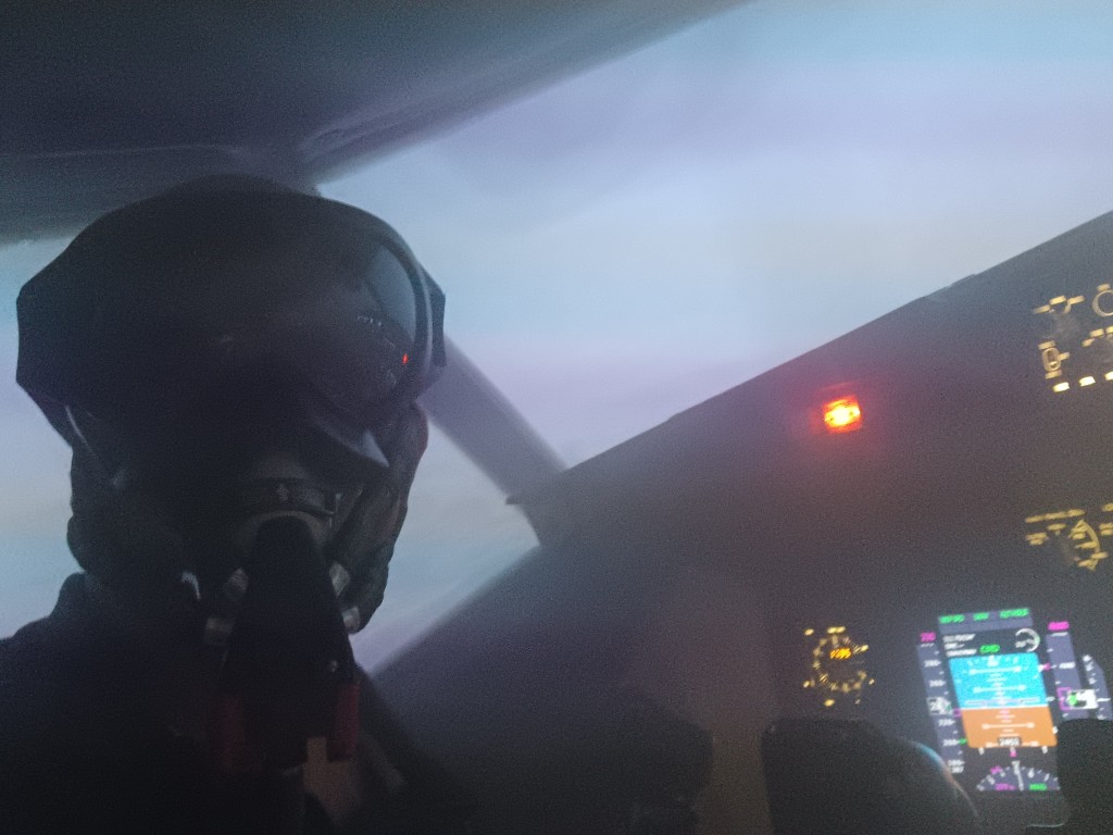
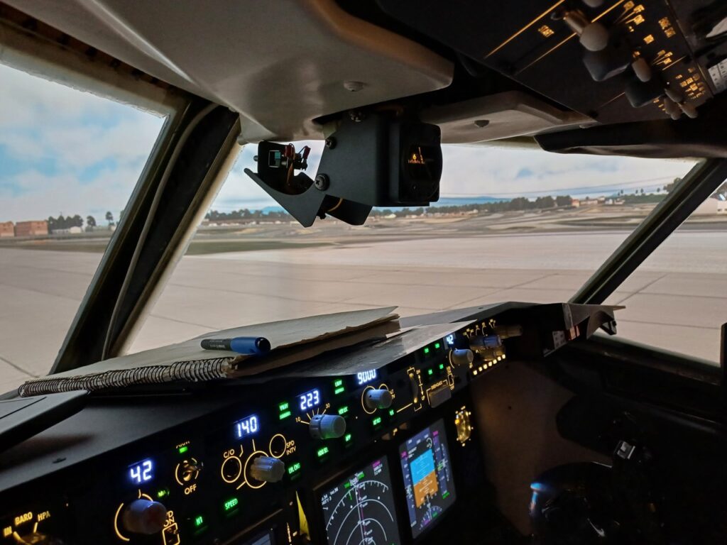
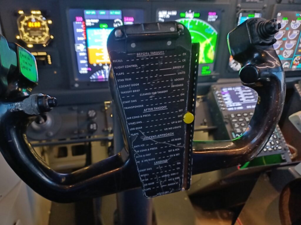
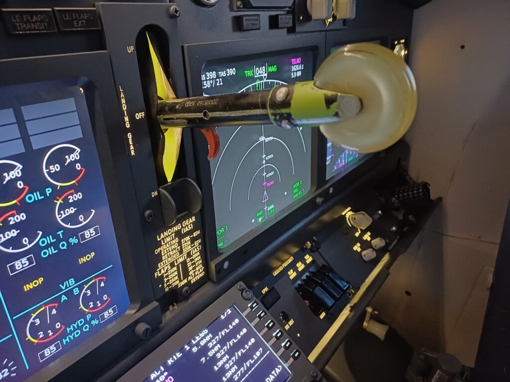
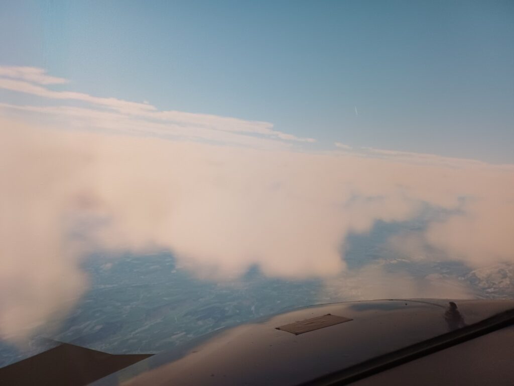
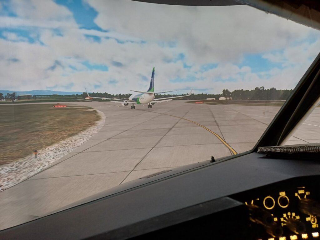
So my 10 year old son and I did a full Smoke in the Cockpit test yesterday and it was a hit. After a regular take off from Zurich Runway 28 and SID VEBIT4W I climbed to FL150 while my young copilot tested the five point safety harness and made sure his oxygen mask did fit his head. After around 2 minutes at FL150 I have started the smoke machine, we both put on the oxygen masks and smoke goggles and I tried to follow the “smoke in the cockpit” non-normal procedure checklist in Chapter 8.8 of the Quick Reference Handbook. It became clear that the fire was not controllable and not in the cockpit itself. I initiated a rapid descent to around 7000 feet and programmed the ILS RWY 14 into the FMS. The situation became quite uncomfortable altough the air we breathed was clean. I also realized that I could not speak to my copilot due to the mask. Connecting all the microphones, headsets and cockpit speakers through the audio control panels is actually my next project, watch out.
The landing was uneventful, although we were a bit fast (170 kts and flaps 15), since I decided to take a shortcut to get the smoky bird down to earth as quickly as possible. Evacuation was started as soon as the aircraft halted on the runway. Was lots of fun! See yourself …
It took about 30 minutes to empty the cockpit from the smoke again and I did not find any remains of the smoke oil so far. So: to be repeated!
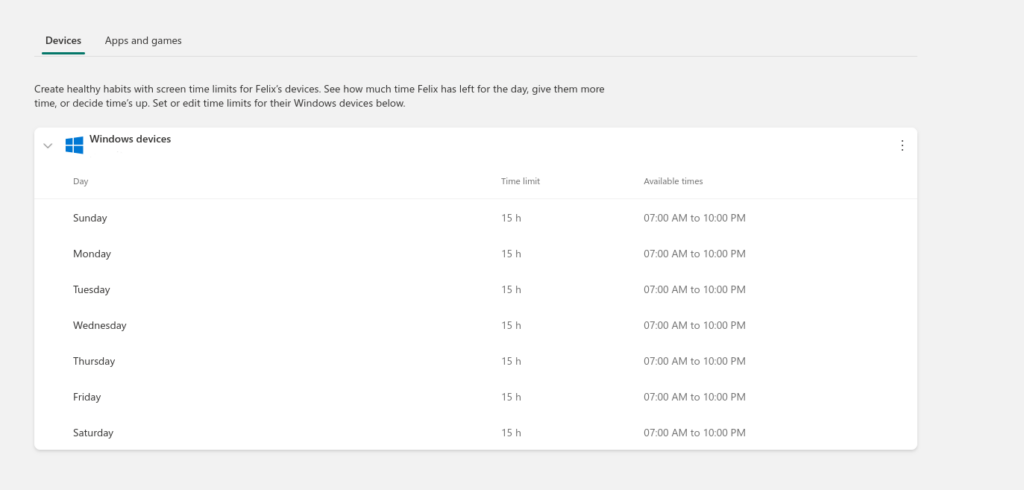
Like many parents we use Microsoft Family Safety to limit screen time of our children. It turns out that the default screen time is …
15 HOURS PER DAY !!!!!
So when you register a Microsoft device (e.g. Windows computer or Xbox) for your 9 year old, the default screen time for your 9 year old is 15 hours. Actually, the default setting is: no control of screen time. Isn’t this hilarious?
Dear Microsoft, it is very nice that you have an App to limit screen time of our children. It is possibly a fact that many parents are overwhelmed with managing the opportunities and threats of today’s technology together with their kids and will not apply screen time at all.
However, wouldn’t it be a service to those parents who care about the health of their children to start with a default screen time of 1 hour upon registration?
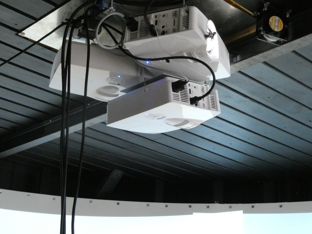
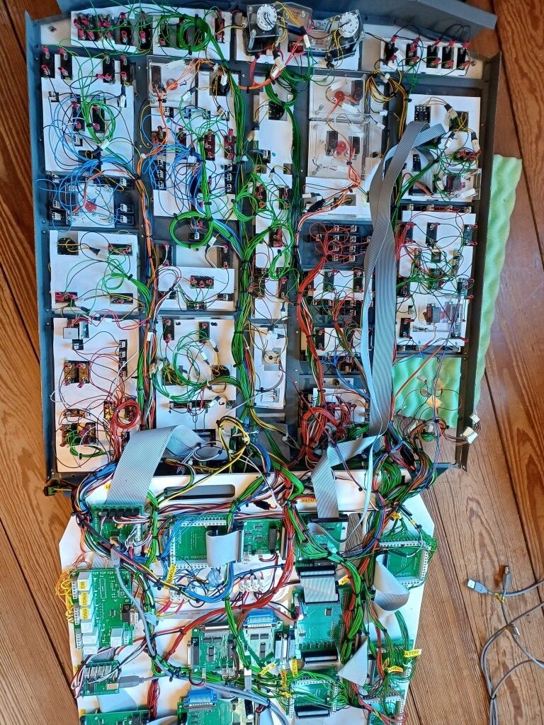
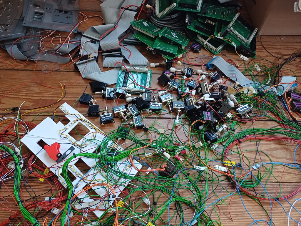
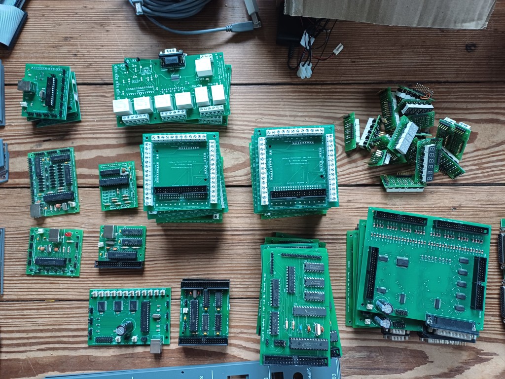
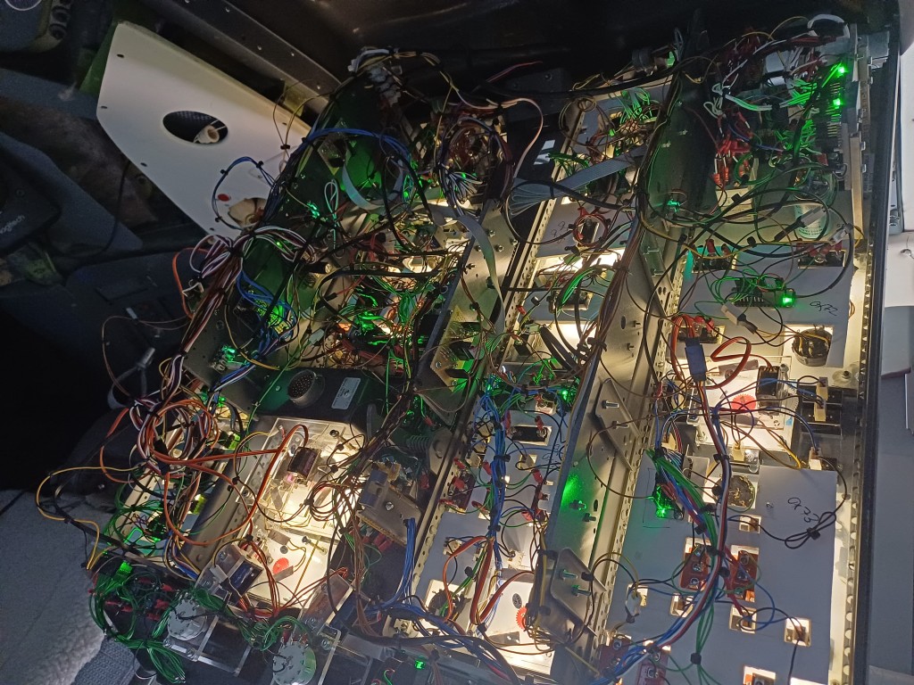
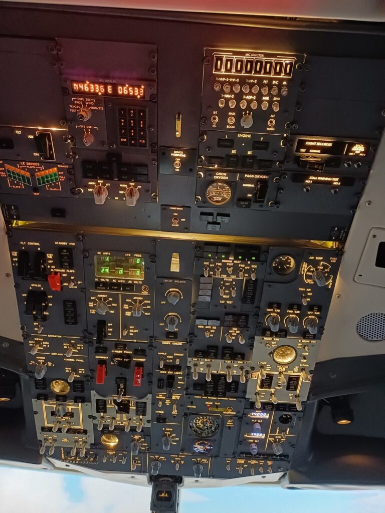
I’ve just removed and replaced the last OpenCockpits Hardware, the Forward Overhead Panel, which was connected via USB to the flight simulator. Apart from the extensive wiring needed, USB devices by OpenCockpits were quite difficult to use because a) their communication protocol is not “Open” as the name misleadingly suggests, and b) the OpenCockpits USB devices have no serial number, thus cannot be distinguished from each other. This last point made is rather difficult to run them reliably, since accessing two servo cards (e.g. one driving the fuel temperature servo and the other driving the cabin pressure servo) was always a lottery. We don’t want to fly by luck, anyway.
Here are some pictures of the “old” Forward Overhead Panel. Nicely built, but too much wiring and occupying 3 USB ports. The last image shows all the hardware panels which were needed.
The new world is called “Ethernet” and Teensy and consists of a universal Teensy firmware which listens to the flight simulator and allows to be on-the-fly programmed for any attached inputs / outputs or daughter boards via the I2C bus. The new Forward Overhead Panel has the following hardware structure:
Teensy 4.1 Controller with Ethernet and I2C interface
19 MCP23017 16 Input / Output boards via I2C
2 PCA9685 PWM / Servo Output boards via I2C
2 HT16K33 7 Segment LED boards via I2C
The new Panel also features 4 Solenoid Switches:
Yaw Damper Switch
Engine 1 Start Switch
Engine 2 Start Switch
Wing Ice Switch
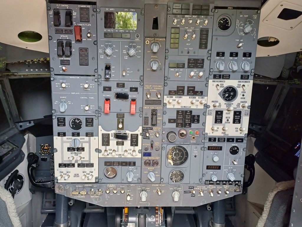
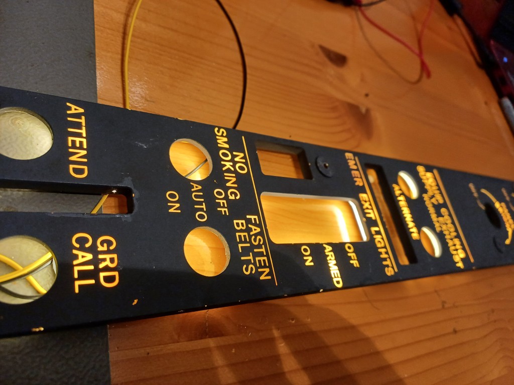
The New Panel also features 16 latched Switches like in the real aircraft and it is mounted on a original B737-300 overhead frame, plus includes three original LED-retrofitted panels and a few original and LED-retrofitted Korry annunciators. Beautiful stuff, see here:
As you can see from the last image, the amount of wiring has not gone to 0. However, each panel can be detached without removing the overhead since each panel only has a 4 wire I2C connector, one Interrupt wire and a 12V backlighting connector. This could be optimized by a generalized panel interface (using e.g. a 6 wire plug).
Flight test is underway, but the new Forward Overhead Panel looks stable so far …
Teensy Code as part of the xpcockpits framework available on Github here.
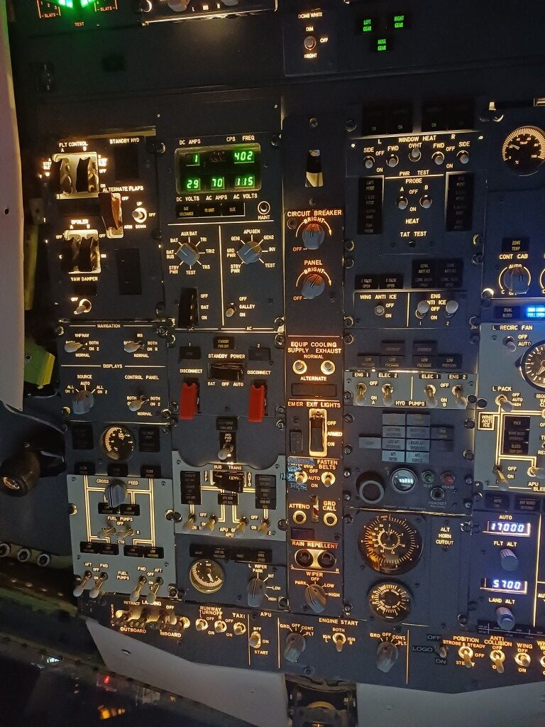
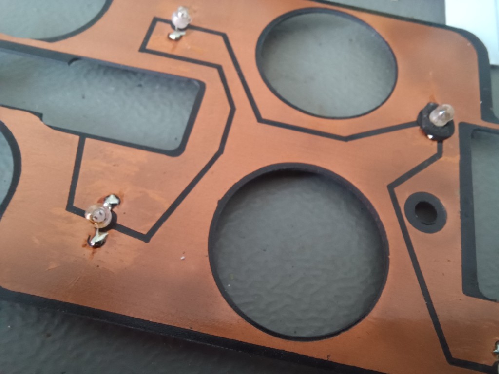
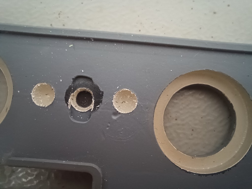
Boeing 737 classic aircraft use cockpit panels which are backlighted by incandescent bulbs. They are driven by 5V (not 28V like all other bulbs, so please don’t burn them, it happened to me). The bulbs are connected in parallel, they are directly soldered onto a PCB and fit through holes into the semi-transparent backplate.
Unfortunately, after 30+ years those incandescent bulbs are not that effective any more and the backlight is rather dim. They also draw quite some power as you can imagine (more than 1A per lightplate).
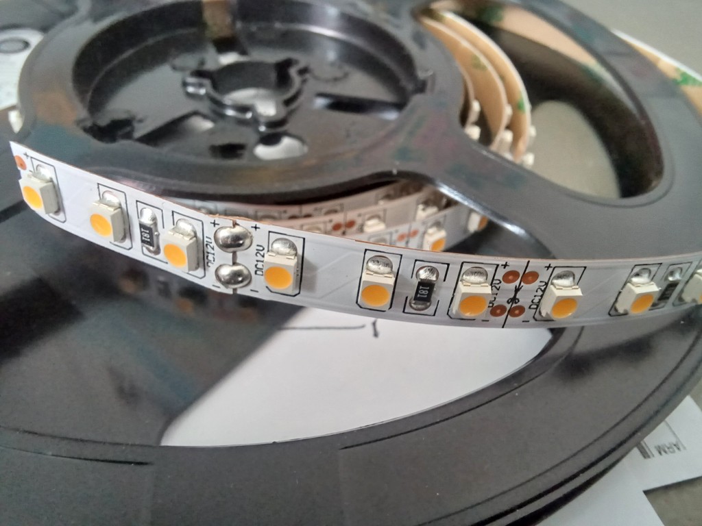
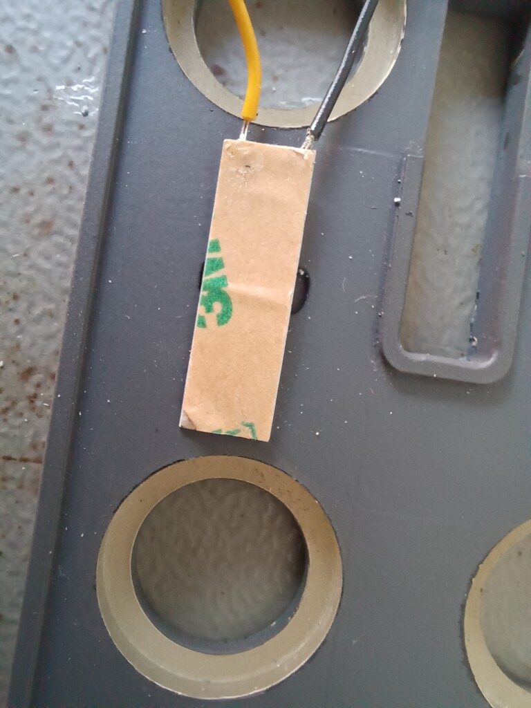
I have now fitted 12V LED strips (using 120 LED’s per meter) in pairs of 3 LED’s to the lightplate and thus had to drill another two holes per bulb hole:
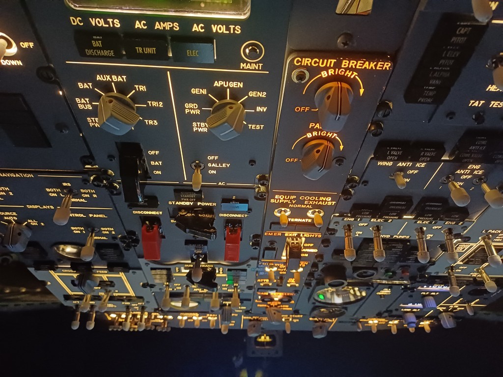
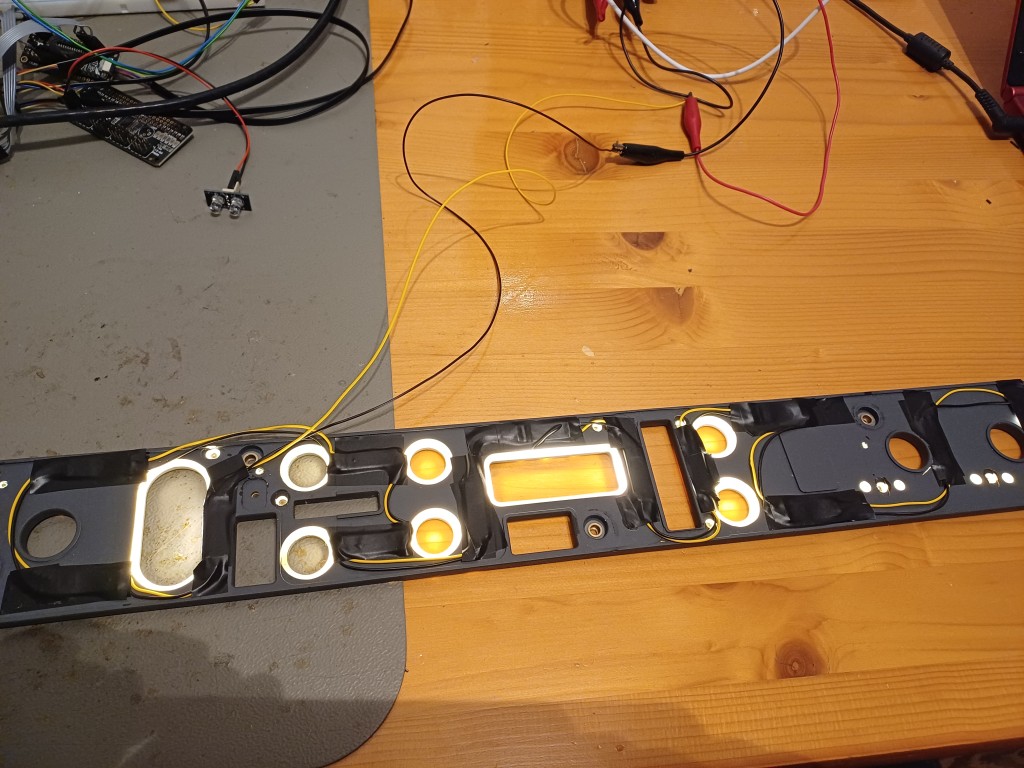
The result is fascinating. A more even distributed backlighting which is much brighter and is dimmable by a PWM mosfet driver from a common microcontroller PWM capable GPIO output. The current drawn by the lightplate went down from 1 A to 0.2 A:
You can for instance use the Joy-IT COM-MOSFET driver to dim the backlight from software. It accepts 3.3V or 5.0V logic inputs.
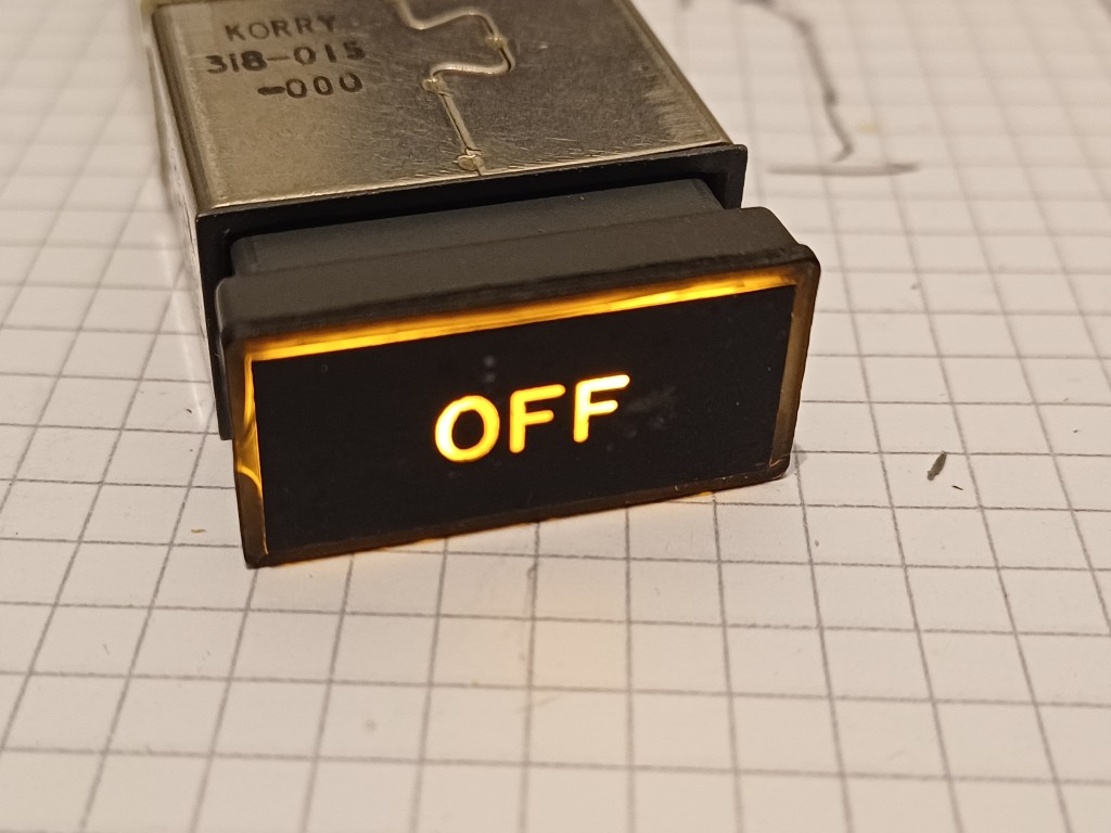
Korry annunciators are used in many larger aircraft. Boeing often uses (or: used, e.g. in the Boeing 737 classic series) the Korry 318 annunciator. It consists of two 28V white light bulbs (Type 387 T1 3/4 Midget Flanged). The annunciator can be pressed, activating a switch to test the annunciator’s light bulbs. The light bulbs can be exchanged easily by pulling the front part of the annunciator from the respective panel … no screw driver needed.
The use of incandescent lamps in annunciator produces a warm light, but 28V is usually not what we use in cockpit building. The annunciator also draws around 80 mA, which is quite a lot.
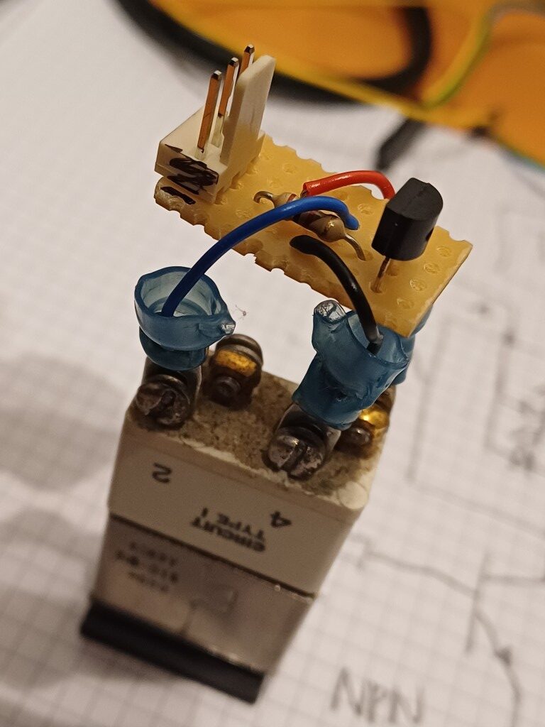
Flaps-to-Approach has demonstrated how to dissasemble those annunciators and how they work. I will now show how to turn the annuciator into a regular 5V device that you can connect to your GPIO pin of any modern microcontroller.
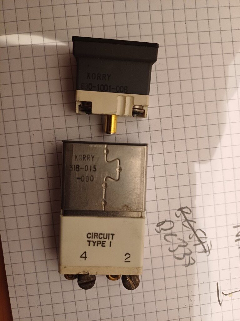
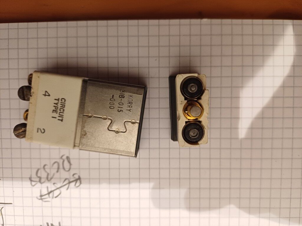
There are two types of Korry 318 annunciators:
Type 1: ground seeking: common power pin and controlled by ground pin
Type 2: power seeking: common ground pin and controlled by power pin
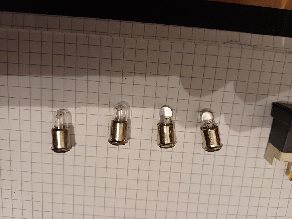
The first step is to replace the lamps with LED’s. This is possible through the company ledlightbulb.net which offers T 1 3/4 midget flanged bulbs with LED’s instead of incandescent lamps:
Please choose the white color LED with 5V dimmable configuration
For Type 1 Korrys please add in the comment field: “center pin negative”
For Type 2 Korrys please add in the comment field: “center pin positive”
You will get the LED replacements as shown below (left are two inandescent bulbs and right are two LED replacements. Put those LED’s into the Korry annunciator and test the circuit using a 5V power supply.
The next task is to build a circuit so that the LED Korry switch can be connected to your microcontroller. The Korry switch LED’s are connected in parallel, require 5V driving power and still draw around 20 mA, which may be too much for your GPIO pin of your microcontroller.
The following schematic is suitable for Type ground seeking Korrys:
The following schematic is suitable for the Type 2 power seeking Korry:
The circuits can be easily put on a small board right next to the Korrys, see here:
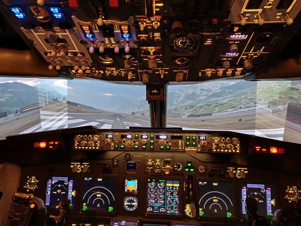
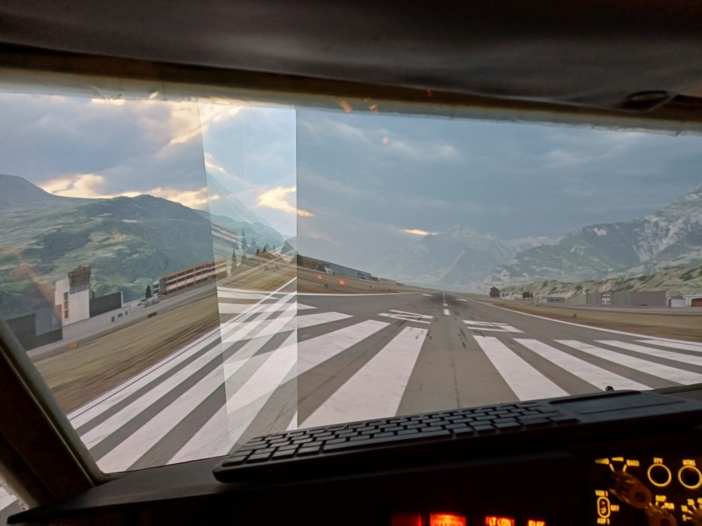
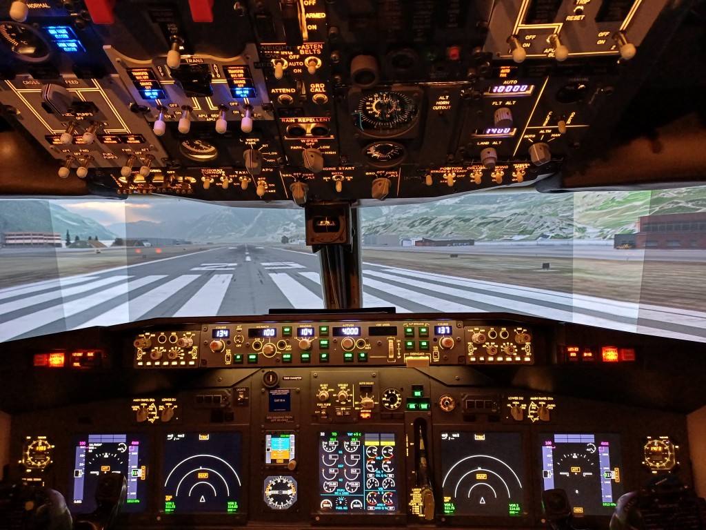
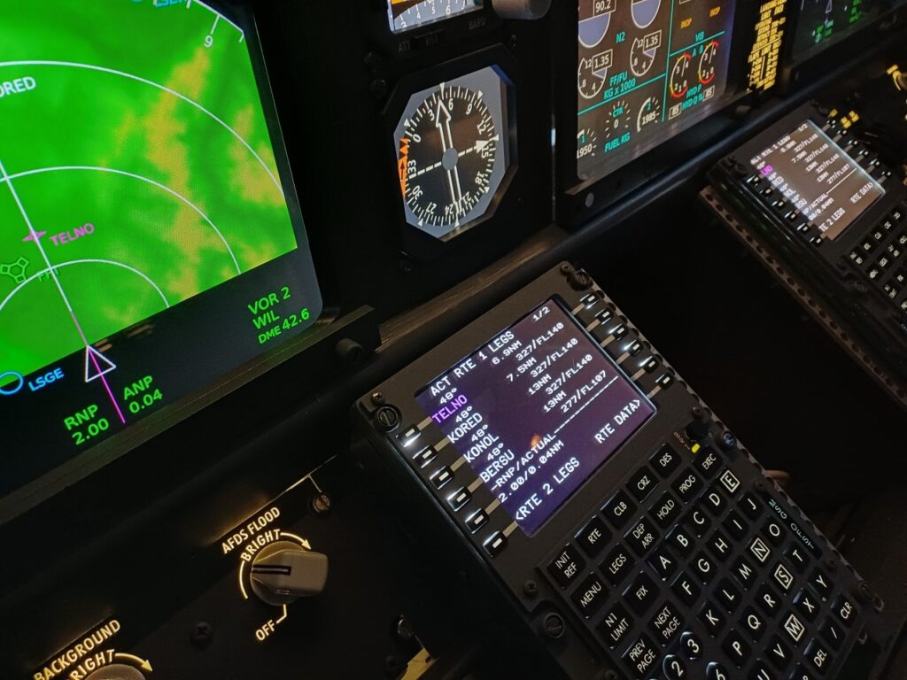
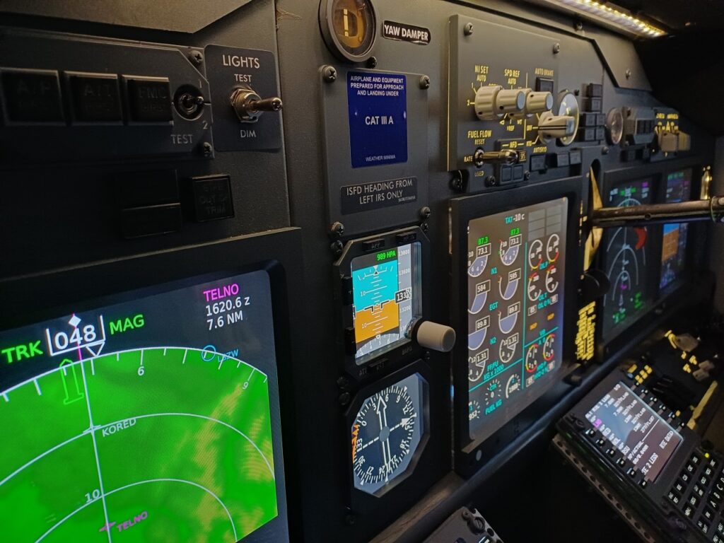
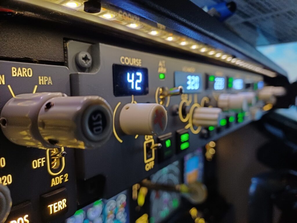
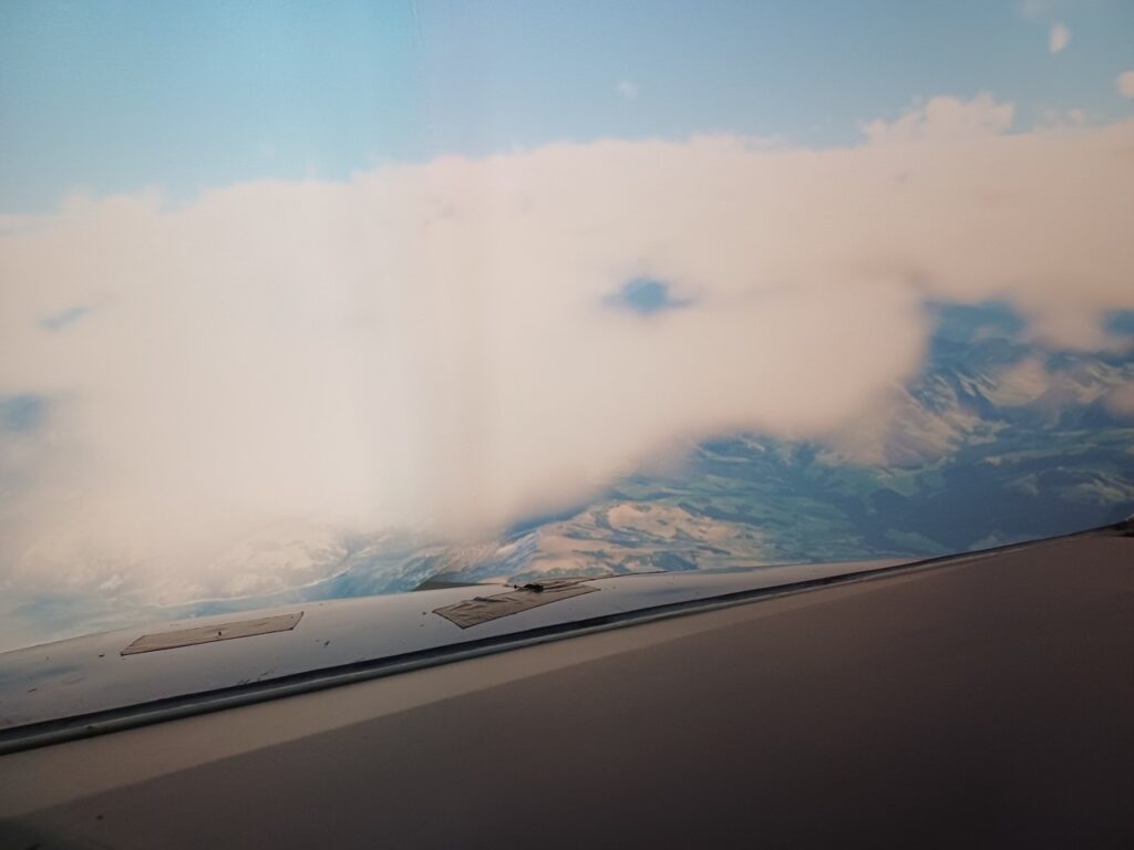
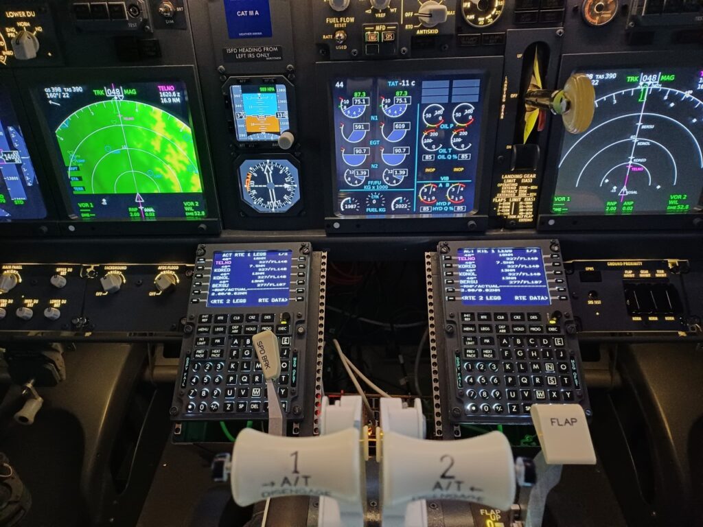
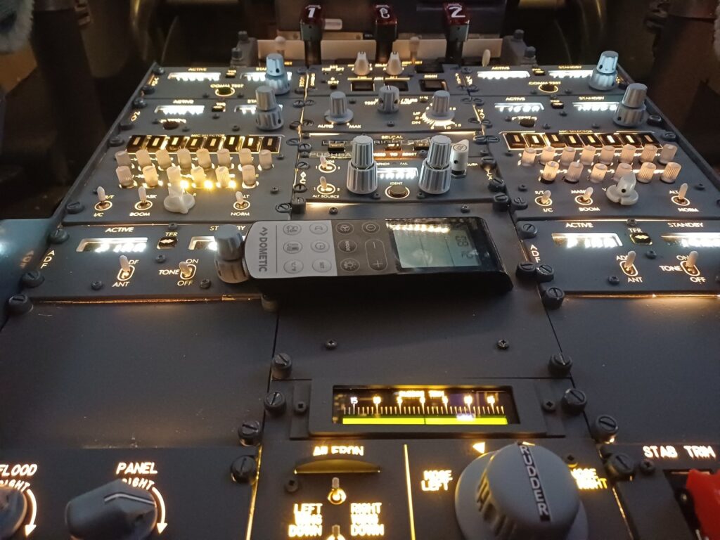
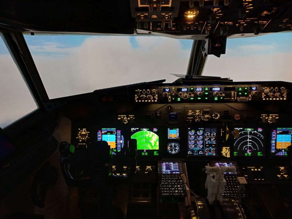
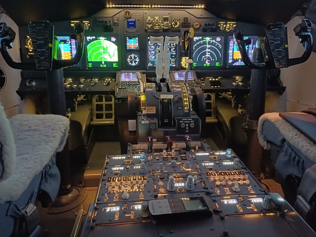
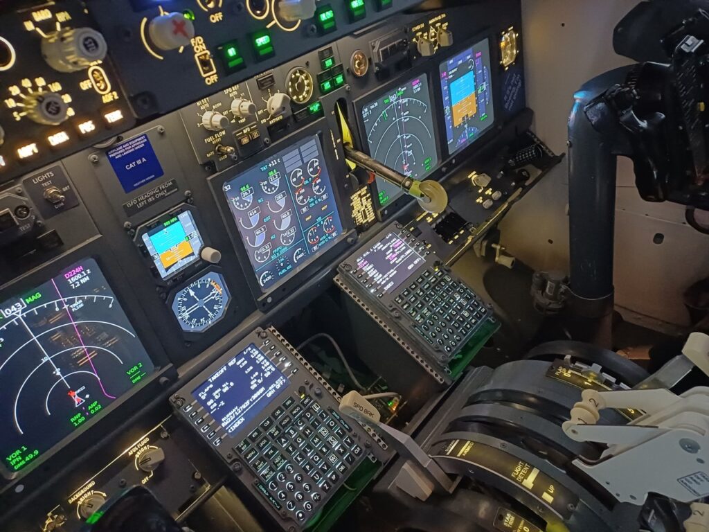
Not many words needed. I’m happy to show you some pictures of my first flight yesterday on 26 March 2024 with the newly rebuilt Flight Simulator Home Cockpit, now featuring a second flight management computer and the newly built aft overhead panel, and, and, and … also many thanks for the VACC (VATSIM Controllers in Switzerland) staff for this greate Geneva to Zurich coverage!
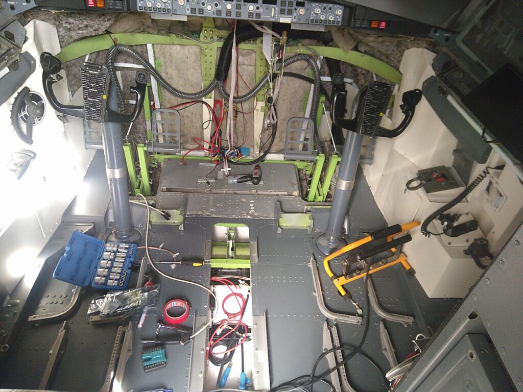
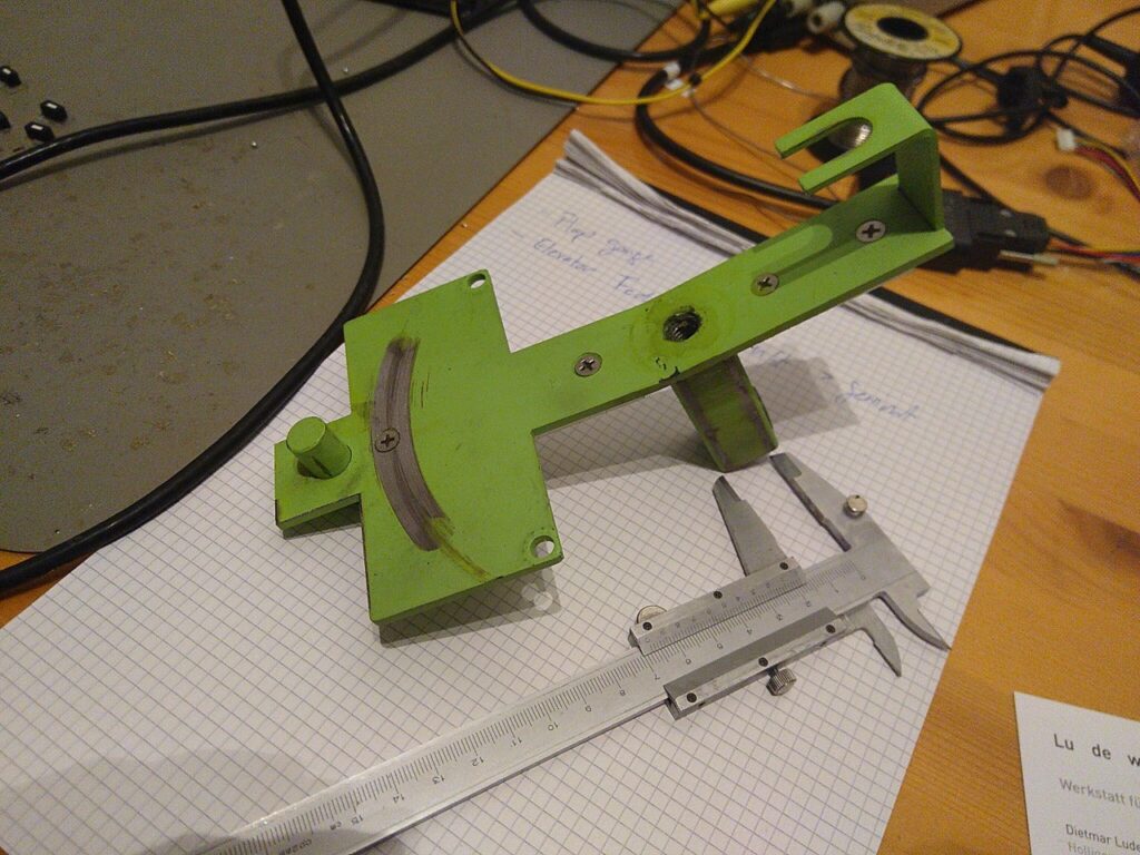
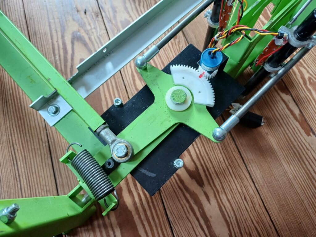
After having almost completely mounted the Sim in a newly built wooden house including a curved 210 degree screen and three projectors, a small metal part of the mechanical rudder pedals broke. Since the B737 sim is mounted in a real cockpit enclosure, there is no way to access the rudder pedal from the front. This meant unmounting the pedestal, throttle quadrant, seats and the main instrument panel MIP first …
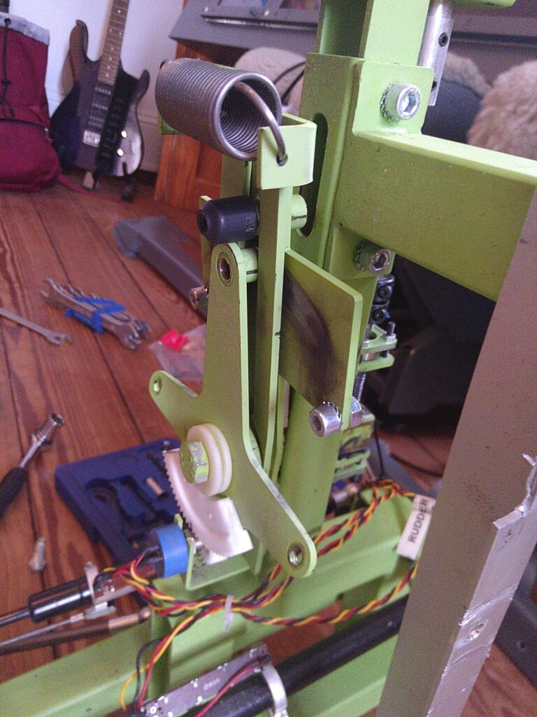
The good thing about such an exercise: each time I have to take apart the Cockpit things can be improved and the rebuilding process becomes easier. The broken part was found, but the supplier of this otherwise great dual linked rudder pedal assembly, SimuJabs from Spain, unfortunately went out of business.
I was very glad to find a nearby wood and metal workshop in 3008 Bern called LU DE WIG, who created a reinforced replica of the broken part in s short time (piece is now painted in black instead of green):
Rebuilding the cockpit (start in front and work your way backwards was a breeze (only around five hours in total):